
User Manual

SDB670 – SERVICE MANUAL TNM-M-E-0032
May 13 Page 24 DESCRIPTION
These units are electrically identical to the SDM600 Mobile and are also fully interchangeable in
the 25 W power group. Control is provided via the 10-way RJ45 connector. Power is supplied via
the power harness connector and RF signals are coupled to the British Naval Connector (BNC)
sockets with double-screened cables.
4.2 F
RONT
P
ANEL
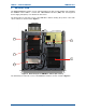
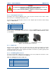
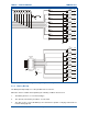
The SDB670 front panel is illustrated below in Figure 4.
Figure 4. SDB670 Front Panel.
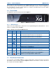
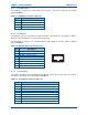
4.2.1 LED Indicators
On the front of the SDB670 base station there are 12 Light Emitting Diode (LED) indicators. There
details are explained below in Table 7.
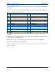
Table 7. Details of Front Panel LED Indicators.
LED Legend
Colour Description
Health
Ì
Green Indicates
Func 1
VM
For Tier II this is a programmable function.
For Tier III this indicates the base is a VAC Master
Func 2
SM
For Tier II this is a programmable function.
For Tier III this indicates the base is a Site Master.
Indicates base is in Analogue Mode
Rx 1 R1 Indicates signal received on Slot 1
Tx 1 T1 Indicates unit is keyed up and transmitting on Slot 1
Power
Indicates the presence of electrical supply voltage.
Tx 2 T2 Red Indicates unit is keyed up and transmitting on Slot 2
Rx 2 R2 Yellow Indicates signal received on Slot 2
Indicates base is in DMR Mode
Func 3
IS
Orange For Tier II this is a programmable function.
For Tier III this indicates the base is an Isolated Site.
Func 4
IB
Orange For Tier II this is a programmable function.
For Tier III this indicates the base is an Isolated Base.
Alarm
Red Indicates a pre-arranged alarm condition exists.
4.3 R
EAR
P
ANEL
C
ONNECTORS
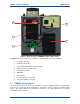
The rear panel of the SDM670 DMR base station showing all the external connections for both the
AC and DC version are shown overleaf in Figures 5 and 6. The functions of each connector on
the rear panel are detailed in Table 8.