
User Manual

SDB670 – SERVICE MANUAL TNM-M-E-0032
May 13 Page 23 DESCRIPTION
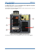
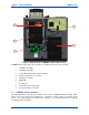
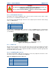
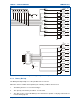
Figure 3. Internal Layout of DMR Base Station (DC version).
In Figures 2 and 3, the main sub-assemblies are numbered and refer to the following:
1. Tx Engine Assembly.
2. Rx Engine Assembly.
3. Control Board Printed Circuit Board (PCB).
4. PSU Assembly (AC version only).
5. Heat Pipe Assembly.
6. MMI PCB.
7. External Fan.
8. Internal Fan (AC version only).
9. Fuse Board (DC version only).
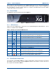
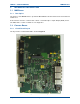
4.1 SDM600
S
UB
-A
SSEMBLIES
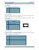
The RF performance of this product is derived from a pair of SDM600 Engine Assembly PCBs
mounted on a Heat sink sub-assembly that is designed to permit continuous operation at full
power. The sub-assembly also provides RF screening, so it is important that it is accurately
assembled and reassembled.
5
2
3
6
1