
User Manual

SDB670 – SERVICE MANUAL TNM-M-E-0032
May 13 Page 17 PRODUCT CODES
2 PRODUCT CODES
This section specifies how the DMR equipment will be coded and labelled, and the structure of
these codes. The following information is displayed on the Type Approval Label located on the
rear panel of the base station.
2.1 O
RDER
C
ODE
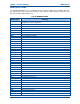
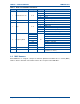
The order code specifies the Transceiver’s model and features. The Order Code structure consists
of eight fields with 11 alphanumeric characters.
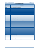
Field 1 Field 2 Field 3 Field 4 Field 5 Field 6 Field 7 Field 8
6 B 1 TU A1 S 0 00
The fields of the order code are broken down as shown below in Table 1.
Table 1. Order Code Information.
Field Description Range Example Explanation
1 Model 0 – Z 6 SDX600 range of products
B Base Station
K SDP660 Portable – Keypad version
M SDM600 Mobile range
2 Type 0 – Z
N SDP650 Portable – Non-keypad version
3 HW Series 0 – Z 1
Used for major changes in mechanics or hardware
builds. 0 = Prototype/Revision 1
AC 136 MHz – 174 MHz
TU 400 MHz – 480 MHz
UW 440 MHz – 520 MHz
4
00
TU
Not Applicable
Includes chassis/case, endplates, sealing
00 Prototype
01 Standard Mobile
02 Black Portable
03 Yellow Portable
04 Red Portable
05 Blue Portable
A1 AC – 25 W
A2 AC – 50 W
A3 AC – 100 W
D1 DC – 25 W
D2 DC – 50 W
5 Mechanics 00 - ZZ
D3 DC – 100 W
Used by factory Program to select/create appropriate
label.
C China
H Harris
(Note 2)
6 Market Code 0 – Z
S Simoco International
(Note 1)
7 HW Option 0 – Z 0
Specifies Option board fitted.
0 = Standard Radio – No Option Board.
8 Spare 00 – ZZ 00 Reserved for future use.
Note 1. Includes labelling suitable for Australia, Europe, USA, Canada.
Note 2. Example of support for rebranded radios.