
User Manual


SGD-SB2025NT-TUM, Part 1
Jan 12 Page 48 ALIGNMENT & TESTING
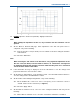
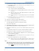
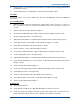
Figure 13. Typical result for Tx Modulation displayed on RTS.
32. DO NOT adjust the ‘VCO Level (VF Audio)’ digital potentiometer.
Note.
When making the adjustment in Para 31, any overshoot near the transitions can be
ignored.
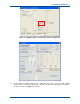
33. On the MxTools Channel Edit page, when adjustment of the 200 Hz square wave is
completed, carry out the following:
33.1. Note the ‘Ref Osc Level (LF Audio)’ level as it will be used when setting the deviation
on all channels.
33.2. Select the ‘OK’ button.
Note.
When selecting the ‘OK’ button in the Para above, if any significant adjustment of the
‘Ref Osc Level (LF Audio)’ has been made in Para 31, an “Information” message will
be displayed advising that changes have been made and they have to be saved and
sent to the base station to take effect.
34. If the Information message is displayed, select the ‘OK’ button to save the changes and
prepare the data to be sent to the base station.
35. On the MxTools main window, on the dynamic tool bar, select the ‘Write Channel’ button to
store the settings back to the SB2025 base station.
36. On the NI ET, on the NI Engineering window, carry out the following:
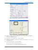
36.1. On the Facilities tab, set the ‘Test Tone’ to a frequency of 1011 Hz and to a level of
−4.4 dB. Set the Route to ‘External’ (see Figure 8).
36.2. Select the ‘Apply’ button.
37. On the MxTools Channel screen, select one of the configured channels and carry out the
following:
37.1. On the MxTools Channel screen, select the ‘Set Software Channel To’ tick button.