
User Manual

SGD-SB2025NT-TUM, Part 1
Jan 12 Page 25 GENERAL DESCRIPTION
CAUTION
The Antenna System must to be protected against lightning by means of an
earthing system and surge protection device.
Do not connect Antenna Lightning conductors to the base station or Mains
Earth.
4.1.2.5 Receiver Input
This is a 50 Ω female N-type socket, which is used for the RF Rx input in duplex operation.
4.1.2.6 High Stability Oscillator Input (BNC)
This is a Bayonet Neill-Concelman (BNC) connector used as the 10 MHz high stability input.
4.1.2.7 Ethernet
The Ethernet socket is a 10/100 base-T RJ45 connection. The Ethernet socket provides a 10Base
Ethernet connection for the NI module and/or the TM module. If only the NI module is fitted, the
connection speed will be 10 Mbps, half duplex. If the TM module is fitted, the connection speed
will be 10/100Mbps as negotiated with the host Ethernet network.
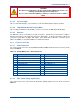
4.1.3 Connector Pin-outs
4.1.3.1 Environment I/O
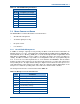
The connector pin-outs for the 20-way Mini Data Ribbon (MDR) Environment I/O socket are shown
below in Table 10.
Table 10. 20-way MDR Socket – Environment I/O.
Pin Function Pin Function
1 Input/Output # 1 11 Input/Output # 9
2 Input/Output # 2 12 Input/Output # 10
3 Input/Output # 3 13 Input/Output # 11
4 Input/Output # 4 14 Input/Output # 12
5 Input/Output # 5 15 Input/Output # 13
6 Input/Output # 6 16 Input/Output # 14
7 Input/Output # 7 17 Input/Output # 15
8 Input/Output # 8 18 Input/Output # 16
9 0 V – Common/Ground 19 0 V – Common/Ground
10 +12 V supply (max 300 mA) 20 +12 V supply (max 300 mA)
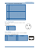
4.1.3.2 GPS (1PPS Timing Signal Input)
The connector pin-outs for the 15-way D GPS/1PPS Timing Signal socket are shown overleaf in
Table 11.