
User Manual

SGD-SB2025NT-TUM, Part 2
Jan 12 Page 87
ALARMS
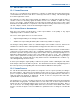
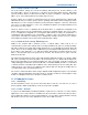
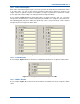
Figure 74. Setting Misc Alarms for a NI.
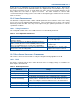
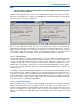
12.3.4 TM Misc Alarms
As an example,
Figure 75
below shows that ‘Duplication’ and ‘PPS’ have been assigned to alarm
status.
Figure 75. Alarms Setup for a TM.
12.4 A
LARM
I
NDICATIONS
12.4.1 Alarm Active
The presence of an alarm condition will be indicated by one or more flashing
Red
borders on the
area(s) of the TM ET main window to indicate the source of the alarm(s). For a Station NI, this is
the Station panel; for a Central NI, this is the ‘Cen #N’ tab; and for the TM itself, this in the ‘TM’ tab.
If the origin of the alarm is an NI which will has a channel relationship, then the tab of the channel
group containing the NI with the alarm will also gain a flashing
Red
border. If a panel or tab was
previously selected so that it had a
Green
border prior to the alarm state, then the border will now
flash alternately
Red
and
Green
.
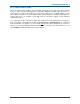
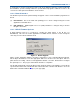
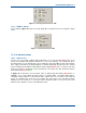
In
Figure 76
overleaf there are two alarms active as indicated by the flashing
Red
borders or
highlights; one is on the TM itself and the other is on Station NI#1. The Station NI#1 alarm is
causing the alarm indication on the Chan #1 tab to appear since it is a member of the Chan #1
group. To determine the exact cause of the alarm, the status view of the unit with the alarm
indication must be examined. For a NI this means clicking the button to open the remote view
window; for the TM this is shown on the TM Status panel.