
User Manual

SGD-SB2025NT-TUM, Part 2
Jan 12 Page 28
TM ET
3.3 U
PPER
A
REA
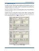
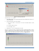
3.3.1 Station NI Panels
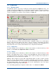
As a minimum, each panel in the upper area of the TM ET will have a numbered button displayed.
This button is the route to the IP address assignment facility as shown in
Section 4.4.3 –
Allocating a Station NI
. A second button, a bar and a round coloured indicator will appear once
the panel has been allocated to an NI, i.e. given the IP address of an NI and “Enabled” (see
Figure 16
below).
The panel border highlight is designed to show extra detail about the Station NI and will not appear
until the panel has been allocated.
Figure 16. Station NI panels.
The functions of each indicator are as follows:
• Vertical Bar:
o
RSSI level, indicated by the height of the
Yellow
bar.
o
Voter override, indicated by a
Blue
bar (see
Section 5.4.2.2 – Voter Override
).
• Round Status indicator:
o
Green
– Normal condition during no signal/idle period.
o
Yellow
– Site selected by “voter”.
o
Red
steady – No network comms.
o
Red
flashing – NI inhibit invoked or no timing signal input.
• The panel border highlight colours:
o
No highlight – this station is not in the currently selected channel.
o
Green
– this station is a member of the selected channel.
o
Red
flashing – an alarm is present or has not been acknowledged.
o
Yellow
flashing – an alarm is present and has been acknowledged.
• Bottom button (no legend):
o
Access to the remote view of a Station NI for engineering purposes.