
User Manual


SGD-SB2025NT-TUM, Part 2
Jan 12 Page 27
TM ET
3 TRAFFIC MANAGER ET
3.1 I
NTRODUCTION
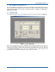
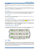
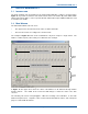
The main operating entry level window to the Solar TM ET application software is shown below in
Figure 15
. It provides a reflection of the Solar network status. The Station NI panels will be blank
until assigned an IP address of the respective NI and enabled whereupon additional indicators and
a control become visible.
3.2 M
AIN
W
INDOW
The main window divides into two areas:
• The upper area is fixed and shows the status of all the Station NI.
• The lower area varies according to the selection made.
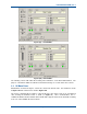
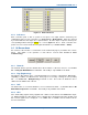
The example in
Figure 22
below shows a TM that has only been setup for a single station. The
number of channel (‘Chn:’) tabs is likely to be different to this example.
Figure 15. TM Main window.
In
Figure 15
, the Upper Area shows the status of all Stations for all channels through “Station
Interface Panels”. The details in the Lower Area will change to reflect the status of the item
selected.
The following sub-sections and paragraphs outline the meaning of the indications on the main
window and panel areas. Separate sections in this manual deal with the actions and subsequent
pages associated with the buttons.
Station Interface Panels
Station Interface Panels
Upper
area
Lower
area