
User Manual

SGD-SB2025NT-TUM, Part 2
Jan 12 Page 40
SOLAR COMMISSIONING
5 SOLAR COMMISSIONING
5.1 C
OMMISSIONING
O
VERVIEW
Solar commissioning falls into two stages:
(a). Configuring the analogue interface of each NI to suit the requirements of the connected
equipment.
(b). Configuring the system parameters to meet the operational requirements.
Stages (a) lies entirely with the NI and comes under ‘Engineering’ settings, which can be set using
the TM ET as well as the NI ET. Stage (b) lies entirely with the TM and can therefore only be set
using the TM ET.
After the basic commissioning is complete there is likely to be a period of optimisation when the
Solar network is “fine tuned” to the IP bearer network. Ultimately, the user may like to consider
ways to enhance the Solar network with the addition of specific features such as Alarms, SNMP or
TM redundancy (the latter two features are special options). These particular topics are dealt with
in their own sections.
5.2 NI
E
NGINEERING
All “Engineering” settings and adjustments that are accessed under the ‘NI Engineering’ window
are available to both the NI ET and TM ET. The settings are stored in the TM, which continually
sends this information as part of the Solar supervisory system. The settings are also held in the
non-volatile memory of each NI, so that the NI can continue to operate in a fall back mode if
isolated from the TM as well as recovering quickly from a loss of power.
These settings are referenced by the NI ‘Address’ as designated in the TM and not the IP address,
although, naturally, the IP address for each NI must match that held in the TM for correct
operation. This means that replacement of an NI is made much more straightforward as the
‘Engineering’ settings will be automatically uploaded when contact with the TM is established.
For example, replacing the NI in Site #4 will result in the original settings for that site being passed
in a few seconds to the replacement unit, which must match the IP address of the original unit (text
labels will take a lot longer as these are given lowest priority).
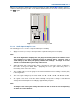
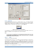
The ‘NI Engineering’ window is accessed by clicking on the ‘Eng’ button on the NI main window –
see
Section 2.6 – NI Button Area
. This action opens a new window that has four pages of
information: ‘Main Audio’, ‘Signalling’, ‘Facilities’ and ‘Environment’. Each page is accessed by
clicking on the tab for that page.
The ‘NI Engineering’ window also has an ‘Eng’ button that must be clicked “IN” before a change
can be made, whereupon the ‘Apply’ button will become active. Any changes in settings will not
become active until the ‘Apply’ button is selected. The ‘NI Engineering’ window is closed by
clicking on the ‘Close’ button or the close icon
in the top right hand corner. Any changes made
but not applied will be lost when the window is closed.
If these pages are viewed through the TM ET there will be an ‘Alarm’ button on the lower area of
the page and extra tabs on the ‘Signalling’ and ‘Environment’ pages – see
Section 12 – Alarms
for full details of these functions.
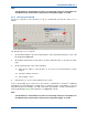
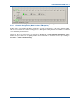
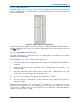
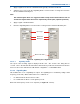
5.2.1 Main Audio
The audio input and output levels and other associated functions are set through this page of the
‘NI Engineering’ facility. The ‘Main Audio’ page of the NI Engineering facility for an Analogue
system is shown overleaf in
Figure 29
.