
User Manual

SGD-SB2025NT-TUM, Part 2
Jan 12 Page 31
TM ET
3.4.2.1 Name
A simple text label that can be entered by the user through ‘Setup’ to identify one channel from
another (see
Section 5.4.1 – Name
).
3.4.2.2 Status
(a). ‘
MTx Key
’ – lit
Yellow
when the channel is keyed either by a control PTT from a Central NI
or as a result of a voted signal being present while T/T is on.
(b). ‘
Talk Thru
’ – lit
Yellow
when the channel has T/T switched on either by an input signal to a
Central NI or a setting of the TM Setup.
(c). ‘
Voted Site
’ – the number of the site currently selected as offering the best incoming signal is
displayed. The number is that of the station panel for that site.
(d). ‘
Voted Level
’ – the Solar RSSI level that is being presented by the site currently selected.
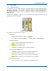
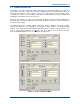
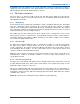
3.4.3 Central NI Status Panel
The status window for Central NI #N (where N is the number of the NI) is selected by clicking on
the ‘Cen:’ N tab (highlighted in
Figure 20
below).
Figure 20. Central NI #1 Status Panel.
The Central NI Status Panel tab gains a
Green
highlight when selected as does the Channel ‘Chn:’
#N tab to which the Central NI has been assigned. All the Station Interface Panels that are
members of the Channel will also gain the
Green
highlight. The example in
Figure 20
shows
Central NI #1 selected, which operates Channel #1.
The facility accessed using the Network button is covered in
Section 4.4.4 – Allocating a Central
NI
. The button (no legend) in the ‘Central’ area provides access to the remote view of the Central
NI for engineering purposes.
3.4.3.1 Central Indicators
(a). ‘
Status
’ – lit
Green
when network communications with the Central NI is established and
Red
if it fails. This may be assigned ‘Alarm’ status – see
Section 12 – Alarms
.
(b). ‘
Tx Key
’ – lit
Yellow
when the Central NI has a PTT applied from a control or console input.
(c). ‘
Talk Thru
’ – lit
Yellow
when the Central NI has the T/T input signal applied. The indicator
and text will be disabled (greyed out) if the Central NI is not configured for control of T/T –
see
Figure 28
as an example and
Section 5.2.2.4 – Isolated Inputs
for details on
configuring Isolated Inputs.