
User Manual

SGD-SB2025NT-TUM, Part 1
Jan 12 Page 26 GENERAL DESCRIPTION
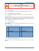
Table 11. 15-way D Socket – GPS/1PPS Timing Signal.
Pin Function
1 +12 V supply (reverse feed & current limited protection)
2 GPS Data I/P – RS422 ‘A’
3 GPS Data I/P – RS422 ‘B’
4 1PPS Signal I/P – RS422 ‘A’
5 1PPS Signal I/P – RS422 ‘B’
6 Not Connected (NC)
7 NC
8 NC
9 NC
10 Data to GPS Rx – RS422 ‘A’ (not normally used)
11 Data to GPS Rx – RS422 ‘B’ (not normally used)
12 0 V – Common/Ground
13 NC
14 1PPS Signal TTL Input – reference to 0 V
15 NC
Shell
Cable screen
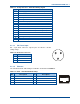
4.1.3.3 DC Power Input
DC – 3-pin male connector: only two pins are wired to suit the
voltage range.
Table 12. DC Power Connector.
Pin Function
1 Unused
2 Ground
3 +13.8 VDC
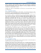
4.1.3.4 Ethernet
The standard network cable wiring for an RJ45 is shown below in Table 13.
Table 13. RJ45 – Standard Network wiring.
Pin
Description Pin
Description
1 Tx Data+, balanced I/P 1 5 NC
2 Tx Data−, balanced I/P 2 6 Rx Data−, balanced O/P 2
3 Rx Data+, balanced O/P 1 7 NC
4 NC 8 NC
1
8
3
1
2
+ -