
User Manual

SGD-SB2025NT-TUM, Part 2
Jan 12 Page 52
SOLAR COMMISSIONING
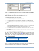
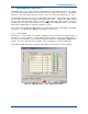
5.2.3.1 Name
This is a user defined text label to aid identification of the NI. The name will be displayed in some
of the TM ET windows to assist the user by confirming that the NI being viewed or altered is the
correct one. To enter or change the text select the ‘Eng’ button (IN), click in the ‘Name’ text box
and amend the text as required (the limit is 19 characters). As for all settings, a change must be
completed by using ‘Apply’.
At this point the text will turn
Blue
until full confirmation is received from the opposing end of the
system, which will take several minutes as text is given lowest priority in the supervisory process.
5.2.3.2 GPS Module
The passage of audio through a NI is dependant upon packet timing, which, in turn, is governed by
the 1PPS timing signal. Therefore, it is important that the configuration and connections match the
type of timing signal to be used, as well as the signal being present and correct before full
commissioning is attempted.
As the GPS/1PPS timing signal connects to a separate and independent sub-module, these
settings will be accessible to other main module(s) that may be fitted to the Solar 2 unit.
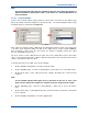
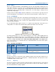
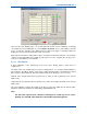
Figure 45. GPS Module Timing Source Menu Options.
The timing signal may be one of two signal voltage types each with or without NMEA data; the
latter must be at RS422 voltage levels. The default setting is ‘422 PPS + NMEA Data’ and
changing to either of the TTL 1PPS options will necessitate that the TTL input is used on the GPS
connector (see
Part 1, Section 4.1.2.1 – GPS (1PPS Timing Signal Input
). When NMEA data is
in the selected option, loss of that data will cause a PPS fail indication even if the 1PPS signal is
still present and correct.
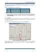
Table 3. NI Timing Signal Options.
1PPS
Signal
NMEA
Data
Selection Option Notes
RS422 RS422 422 PPS + NMEA Data Setting for use with GPS Ae/Rx
RS422 None 422 PPS Only
TTL RS422 TTL PPS + NMEA Data
TTL None TTL PPS Only
The TTL I/P connection must be used if one of
these two options is selected
5.2.3.3 Test Tone
5.2.3.3.1 Level
The test tone level has 11 fixed values and is calibrated relative to the peak audio output level (see
Section 5.3.2.4
). It has a range of 0 dB (peak) to −10 dB (below peak) in 1 db steps plus a step of
-4.4 dB which equates to 60% of PSL.
5.2.3.3.2 Frequency
The test tone frequency range is 300 Hz to 2500 Hz and the required frequency is entered in the
box in Hz. Entering a value outside this range other than zero will cause the setting to change to
the nearest limit when the setting is applied.