
Service Manual


Page 4.7
3 ~ TECHNICAL DESCRIPTION
4.4 C
ONTROL
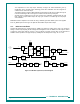
Refer to Figure 4-4.
4.4.1
DSP and PLA
The SRP9100 transceiver operates under the control of a DSP (U201) and PLA (U300) combination that
together with a number of other dedicated devices perform all the operational and processing functions
required by the radio. The PLA is configured by the DSP under software control to provide the following
functions:
• Channel set-up of all operating frequencies
• Modulation processing and filtering
• De-modulation processing and filtering
• Tx power output reference
• Modulation Balance adjustment
• Receiver front-end tuning
• Serial communications with alignment tool, microphone and control head
• Modem functionality for data modulation
• All signalling / CTCSS generation and decoding
•
DSP Crystal Oscillator control
• Receiver muting control
• RSSI / AGC control
• AFC
• Tx / Rx switching and PTT control
• PLL lock detect
• Audio switching
• Power On/Off control
• Interface functionality with Option Boards and External Devices
• Battery voltage and Tx current monitor
4.4.2
DSP Clock Oscillator
The DSP is clocked by a 15.360MHz oscillator that consists of crystal X200 and an internal DSP oscillator.
Q200 forms a crystal switching circuit with C205 which, when activated by a command from the PLA, steers the
oscillator away from potential interfering frequencies.
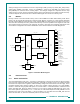
4.4.3
PLA PWM
The PLA must supply several analogue signals to control radio tuning. It does this with several Pulse Width
Modulated (PWM) outputs.
The front-end tune signals (TUNE1-TUNE4) originate from the PLA in the form of PWM signals. The values for
these signals are stored in flash memory from radio alignment and selected depending on the channel that the
radio is currently tuned to. These signals are integrated by RC networks to provide the analogue tuning
voltages that are ultimately applied to the tuning varicap diodes.
Other analogue PWM derived signals used are transmitter power (TX_PWR), receiver AGC voltage (AGC),
LED’s (RED/GREEN) and modulation balance (MOD_BAL).
Analogue inputs are monitored by comparators and a ramp generator that is derived from a PWM signal at the
PLA. Four comparators comprising U301A-D have their non-inverting inputs connected to a ramp voltage
generator.