
Service Manual


Page 4.6
3 ~ TECHNICAL DESCRIPTION
Tool. Adjustment of the ramp slope effectively changes the Phase Modulator gain by
modification of the Schmitt Trigger switching points after modulation from the Integrator is
combined to the saw tooth ramp.
The divided reference signal is differentiated and discharges C744 via Q711 after which Q711
is turned off allowing C744 to recharge via constant current source Q712/Q713.
- Schmitt Trigger comprising Q714 to Q716 converts the modulation combined with the saw
tooth ramp to a square wave output, the duty cycle of which is controlled by the ramp slope
and modulation.
Modulation balance adjustment is carried out using a CODEC generated 100Hz square wave applied
to the TX_MOD input and set to give an optimum demodulated square wave output.
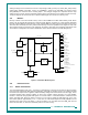
4.3.6
Reference Oscillator
TCXO U700 determines the overall frequency stability and frequency setting of the radio. The frequency
setting is achieved by adjusting its ADJ voltage with the Alignment Tool. In addition, the ADJ input is used in
a frequency control loop with the receiver I and Q signals to provide receiver AFC. U700 operates at
14.4MHz and is specified at ±2.0ppm frequency stability over the temperature range -30° to +75°C.
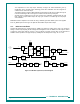
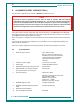
90MHz
VCO Q402
Synthesiser
U701
RX/TX VCO
Q600/ Q602
TX/RX
Switch
D601/
D611
VCO
Buffer
Q604/
Q605
Data From
DSP
Phase
Modulator
Q714-
Q716
Ramp
Generator
Q711-
Q713
Integrator
U711A
TX_MOD
MOD_BAL
Prog.
Divider
U710
Buffer
Q710
14.4MHz
Reference
Oscillator
U700
To TX Buffer
REF
PLL Loop
Filter
VCO Neg
Bias
Supply
Q700-
Q703
CPP
CPPF
DOUT
VCAP_BIAS
AUX_LO2
AUX_CP
Divide 32 (UHF)
Divide 64 (VHF)
Synth
Buffer
Q607
SYNTH
LO1_RX
Q
RX/TX
Switch
U800A
I
Internal
External
TX Audio
Switch
Internal Mic.
External Audio
ADC/DAC
CODEC
U820
TX_MOD
To IQ
Demodulator
U400
LO2
AFC
from
PLA
To RX Mixer
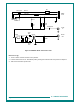
Figure 4-3 VHF/UHF Synthesiser, Block Diagram