
Owner`s manual


New Shallow Well Installation 5
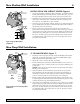
SHALLOW WELL JET PUMP INSTALLATIONS
• Have a vertical depth between the pump and the water being pumped
of 25’ or less.
• Have one pipe from the well to the pump case.
• Can be installed in a bored or drilled well, or in a driven well.
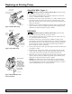
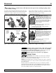
WELL POINT INSTALLATION (Figure 4)
1. Drive the well, using “drive couplings” and a “drive cap”. “Drive fit-
tings” are threaded all the way through and allow the pipe ends to butt
against each other so that the driving force of the maul is carried by the
pipe and not by the threads. The ordinary fittings found in hardware
stores are not threaded all the way through the fitting and can collapse
under impact. “Drive fittings” are also smoother than standard plumbing
fittings, making ground penetration easier.
2. Mount the pump as close to the well as possible.
3. Use the fewest possible fittings (especially elbows) when connecting the
pipe from the well point to the pump suction port. The suction pipe
should be at least as large as the suction port on the pump (include a
check valve). Support the pipe so that there are no dips or sags in the
pipe, so it doesn’t strain the pump body, and so that it slopes slightly
upward from the well to the pump (high spots can cause air pockets
which can air lock the pump). Seal the suction pipe joints with teflon
tape. Joints must be air- and water-tight. If the suction pipe can suck air,
the pump cannot pull water from the well. If one well point does not
supply enough water, consider connecting two or three well points to
one suction pipe.
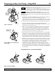
CASED WELL INSTALLATION, 2” OR LARGER
CASING (Figure 5)
1. Mount the pump as close to the well as possible.
2. Assemble the foot valve, strainer, and well pipe. Make sure that the foot
valve works freely.
3. Lower the pipe into the well until the strainer is five feet above the bot-
tom of the well. It should also be at least 10 feet below the well’s water
level while the pump is running in order to prevent the pump from
sucking air. Install a sanitary well seal.
4. Install a priming tee, priming plug, and suction pipe to the pump.
Connect the pipe from the well to the pump suction port, using the
fewest possible fittings (especially elbows) as fittings increase friction in
the pipe. The suction pipe should be at least as large as the suction port
on the pump. Use teflon tape on threaded pipe joints. Joints must be air-
and water-tight. If the suction pipe can suck air, the pump cannot pull
water from the well. Support the pipe so that there are no dips or sags in
the pipe, so it doesn’t strain the pump body, and so that it slopes slightly
upward from the well to the pump (high spots can cause air pockets
which can air lock the pump).
For parts or assistance, call Simer Customer Service at 1-800-468-7867 / 1-800-546-7867
To Household
Water System
Not
to
Scale
Check
Valve
Relief
Valve
2097 0497 SIM
Drive
Coupling
Drive
Point
Drive point below
water level
Priming
Tee and
Plug
To Household
Water System
Not
to
Scal
e
Check
Valve
Relief
Valve
4033 0801
Suction Pipe
From Well
Priming
Tee and
Plug
Well
Casing
Foot
Valve
Sanitary
Well Seal
Strainer
5-10'
At least
10'
Figure 5:Typical Cased Well
Installation
Figure 4:Typical Well-Point
Installation