
hardware design v1.00


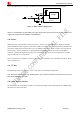
Table Of Contents
- Contents
- Version History
- 1 Introduction
- 2 SIM968 Overview
- 3 Package Information
- 4 GSM Application Interface
- 4.1 GSM Power Supply
- 4.2 Power on/down Scenarios
- 4.3 Power Saving Mode
- 4.4 Charging Interface
- 4.5 RTC Backup
- 4.6 Serial Interfaces
- 4.7 Audio Interfaces
- 4.8 SIM Card Interface
- 4.9 LCD Display/SPI Interface
- 4.10 Keypad Interface
- 4.11 ADC
- 4.12 RI Behaviors
- 4.13 Network Status Indication
- 4.14 General Purpose Input/Output (GPIO)
- 4.15 External Reset
- 4.16 PWM
- 4.17 I2C Bus
- 4.18 GSM Antenna Interface
- 5 GNSS Application Interface
- 6 Electrical, Reliability and Radio Characteristics
- 6.1 Absolute Maximum Ratings
- 6.2 Recommended Operating Conditions
- 6.3 Digital Interface Characteristics
- 6.4 SIM Card Interface Characteristics
- 6.5 VDD_EXT Characteristics
- 6.6 SIM_VDD Characteristics
- 6.7 VRTC Characteristics
- 6.8 Current Consumption (VBAT = 3.8V)
- 6.9 Electro-Static Discharge
- 6.10 Radio Characteristics
- 6.11 Module label information
- Appendix

Smart Machine Smart Decision
close to the NRESET pin is strongly recommended. A reference circuit is shown in the following figure.
Figure 37: Reset reference design circuit
NOTE: It is recommended to cut off the VBAT power supply directly instead of using external reset pin when SIM968 can not
respond to the AT command “AT+CPOWD=1” and PWRKEY pin.
4.16 PWM
SIM968 provides 3 PWMs which can be used to drive a vibrator, and a backlight LED for display or keyboard.
PWM1 and PWM2 output frequency varies from 25.6KHz to 3.25MHz.Two 7-bit unsigned binary parameters are
used for the output period and for the duty cycle. The PWM3 for the buzzer outputs a square wave at the desired
tone frequency. The tone frequencies are programmable from 200 Hz to 5 kHz and can be re-programmed
on-the-fly to generate monophonic audio ring tones or alert tones. The tone level can be adjusted over a 24 dB
range in 4 dB steps, or it can be muted.
The AT command “AT + SPWM” is used to set the output period and duty cycle of the PWM. For details, please
refer to document [1].
4.17 I
2
C Bus
The SIM968 provides an I
2
C interface which is only used in the embedded AT application.
Note: This function is not supported in the standard firmware. If user wants this function, the firmware must be customized.
Please contact SIMCom for more details.
4.18 GSM Antenna Interface
The RF interface has an impedance of 50Ω. To suit the physical design of individual applications, SIM968 offers
the interface as GSM_ANT PAD.
SIM968_Hardware Design_V1.00 2013.02.25
40