
hardware design v1.00


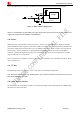
Table Of Contents
- Contents
- Version History
- 1 Introduction
- 2 SIM968 Overview
- 3 Package Information
- 4 GSM Application Interface
- 4.1 GSM Power Supply
- 4.2 Power on/down Scenarios
- 4.3 Power Saving Mode
- 4.4 Charging Interface
- 4.5 RTC Backup
- 4.6 Serial Interfaces
- 4.7 Audio Interfaces
- 4.8 SIM Card Interface
- 4.9 LCD Display/SPI Interface
- 4.10 Keypad Interface
- 4.11 ADC
- 4.12 RI Behaviors
- 4.13 Network Status Indication
- 4.14 General Purpose Input/Output (GPIO)
- 4.15 External Reset
- 4.16 PWM
- 4.17 I2C Bus
- 4.18 GSM Antenna Interface
- 5 GNSS Application Interface
- 6 Electrical, Reliability and Radio Characteristics
- 6.1 Absolute Maximum Ratings
- 6.2 Recommended Operating Conditions
- 6.3 Digital Interface Characteristics
- 6.4 SIM Card Interface Characteristics
- 6.5 VDD_EXT Characteristics
- 6.6 SIM_VDD Characteristics
- 6.7 VRTC Characteristics
- 6.8 Current Consumption (VBAT = 3.8V)
- 6.9 Electro-Static Discharge
- 6.10 Radio Characteristics
- 6.11 Module label information
- Appendix

Smart Machine Smart Decision
Figure 35: Reference circuit of NETLIGHT
4.14 General Purpose Input/Output (GPIO)
SIM968 provides up to 6 GPIO pins. The output voltage level of the GPIO can be set by the AT command “AT+
SGPIO”. The input voltage level of the GPIO can also be read by the AT command “AT+ SGPIO”. For more
details, please refer to document [1].
Table 18: Pin definition of the GPIO interface
Pin name Pin number Default function Second function Default state
GPIO1/ KBR0 31 GPIO1 KBR0 Output, pull down
GPIO2/ KBR1 32 GPIO2 KBR1 Output, pull down
GPIO3/ KBR2 33 GPIO3 KBR2 Output, pull down
GPIO4/ KBC0 34 GPIO4 KBC0 Output, pull down
GPIO5/ KBC1 35 GPIO5 KBC1 Output, pull down
GPIO6/ KBC2 36 GPIO6 KBC2 Output, pull down
4.15 External Reset
The external NRESET pin is used to reset the module. This function is used as an emergency reset only when AT
command “AT+CPOWD=1” and the PWRKEY pin have no effect. The NRESET pin could be pulled down to
reset the module. The reset timing is illustrated in the following figure.
Figure 36: Reset timing
This pin is already pulled up in the module, so the external pull-up resistor is not necessary. A 100nF capacitor
SIM968_Hardware Design_V1.00 2013.02.25
39