
hardware design v1.00


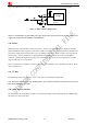
Table Of Contents
- Contents
- Version History
- 1 Introduction
- 2 SIM968 Overview
- 3 Package Information
- 4 GSM Application Interface
- 4.1 GSM Power Supply
- 4.2 Power on/down Scenarios
- 4.3 Power Saving Mode
- 4.4 Charging Interface
- 4.5 RTC Backup
- 4.6 Serial Interfaces
- 4.7 Audio Interfaces
- 4.8 SIM Card Interface
- 4.9 LCD Display/SPI Interface
- 4.10 Keypad Interface
- 4.11 ADC
- 4.12 RI Behaviors
- 4.13 Network Status Indication
- 4.14 General Purpose Input/Output (GPIO)
- 4.15 External Reset
- 4.16 PWM
- 4.17 I2C Bus
- 4.18 GSM Antenna Interface
- 5 GNSS Application Interface
- 6 Electrical, Reliability and Radio Characteristics
- 6.1 Absolute Maximum Ratings
- 6.2 Recommended Operating Conditions
- 6.3 Digital Interface Characteristics
- 6.4 SIM Card Interface Characteristics
- 6.5 VDD_EXT Characteristics
- 6.6 SIM_VDD Characteristics
- 6.7 VRTC Characteristics
- 6.8 Current Consumption (VBAT = 3.8V)
- 6.9 Electro-Static Discharge
- 6.10 Radio Characteristics
- 6.11 Module label information
- Appendix

Smart Machine Smart Decision
C7 SIM_DATA SIM card data I/O
C8 SIM_PRESENCE Detect SIM card presence
4.9 LCD Display/SPI Interface
SIM968 provides a serial LCD display interface. It could also be used as SPI interface in the embedded AT
application. For details about embedded AT application, please refer to document [7].
Note: This function is not supported in the standard firmware. If user wants this function, the firmware must be customized.
Please contact SIMCom for more details.
4.10 Keypad Interface
The keypad interface consists of 3 keypad column outputs and 3 keypad row inputs. The basic configuration is 3
keypad columns and 3 keypad rows, total 9 keys.
Table 14: Pin definition of the keypad interface
Pin name Pin number Default function Second function Default state
GPIO1/ KBR0 31 GPIO1 Output, Pull down
GPIO2/ KBR1
SIM968_Hardware Design_V1.00 2013.02.25
36
The keypad interface allows a direct external matrix connection. A typical recommended circuit of the keypad is
shown in the following figure.
Figure 30: Reference circuit of the keypad interface
Note: This function is not supported in the standard firmware. If user wants this function, the firmware must be customized.
Please contact SIMCom for more details.
32 GPIO2 Output, Pull down
GPIO3/ KBR2 33 GPIO3 Output, Pull down
GPIO4/ KBC0 34 GPIO4 Output, Pull down
GPIO5/ KBC1 35 GPIO5 Output, Pull down
GPIO6/ KBC2
Keypad matrix
36 GPIO6 Output, Pull down