
hardware design v1.00

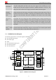


Table Of Contents
- Contents
- Version History
- 1 Introduction
- 2 SIM968 Overview
- 3 Package Information
- 4 GSM Application Interface
- 4.1 GSM Power Supply
- 4.2 Power on/down Scenarios
- 4.3 Power Saving Mode
- 4.4 Charging Interface
- 4.5 RTC Backup
- 4.6 Serial Interfaces
- 4.7 Audio Interfaces
- 4.8 SIM Card Interface
- 4.9 LCD Display/SPI Interface
- 4.10 Keypad Interface
- 4.11 ADC
- 4.12 RI Behaviors
- 4.13 Network Status Indication
- 4.14 General Purpose Input/Output (GPIO)
- 4.15 External Reset
- 4.16 PWM
- 4.17 I2C Bus
- 4.18 GSM Antenna Interface
- 5 GNSS Application Interface
- 6 Electrical, Reliability and Radio Characteristics
- 6.1 Absolute Maximum Ratings
- 6.2 Recommended Operating Conditions
- 6.3 Digital Interface Characteristics
- 6.4 SIM Card Interface Characteristics
- 6.5 VDD_EXT Characteristics
- 6.6 SIM_VDD Characteristics
- 6.7 VRTC Characteristics
- 6.8 Current Consumption (VBAT = 3.8V)
- 6.9 Electro-Static Discharge
- 6.10 Radio Characteristics
- 6.11 Module label information
- Appendix

Smart Machine Smart Decision
controlled to 50Ω.
GPS_ANT 79 I GNSS radio antenna connection
Impendence must be
controlled to 50Ω.
RF_SYNS 53 O RF synchronization If unused, keep open
Other interface
RESET 4 I GSM Reset input, active low If unused, keep open.
AADET_N 46 I GNSS Active Antenna Detect If unused, keep open.
GPS_WAKEUP 54 I
GNSS engine wake up from Backup
mode, active High.
If unused, keep open.
NC 45
This pin should be kept
open.
Not Connected
3.3 Package Dimensions
Figure 3: Dimensions of SIM968(Unit: mm)
SIM968_Hardware Design_V1.00 2013.02.25
16