
hardware design v1.00

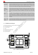


Table Of Contents
- Contents
- Version History
- 1 Introduction
- 2 SIM968 Overview
- 3 Package Information
- 4 GSM Application Interface
- 4.1 GSM Power Supply
- 4.2 Power on/down Scenarios
- 4.3 Power Saving Mode
- 4.4 Charging Interface
- 4.5 RTC Backup
- 4.6 Serial Interfaces
- 4.7 Audio Interfaces
- 4.8 SIM Card Interface
- 4.9 LCD Display/SPI Interface
- 4.10 Keypad Interface
- 4.11 ADC
- 4.12 RI Behaviors
- 4.13 Network Status Indication
- 4.14 General Purpose Input/Output (GPIO)
- 4.15 External Reset
- 4.16 PWM
- 4.17 I2C Bus
- 4.18 GSM Antenna Interface
- 5 GNSS Application Interface
- 6 Electrical, Reliability and Radio Characteristics
- 6.1 Absolute Maximum Ratings
- 6.2 Recommended Operating Conditions
- 6.3 Digital Interface Characteristics
- 6.4 SIM Card Interface Characteristics
- 6.5 VDD_EXT Characteristics
- 6.6 SIM_VDD Characteristics
- 6.7 VRTC Characteristics
- 6.8 Current Consumption (VBAT = 3.8V)
- 6.9 Electro-Static Discharge
- 6.10 Radio Characteristics
- 6.11 Module label information
- Appendix

Smart Machine Smart Decision
Normal power down by sending the AT command “AT+CPOWD=1” or using the PWRKEY.
The power management unit shuts down the power supply for the baseband part of the
module, and only the power supply for the RTC is remained. Software is not active. The
serial port is not accessible. Power supply (connected to VBAT) remains applied.
Power down
AT command “AT+CFUN” can be used to set the module to a minimum functionality mode
without removing the power supply. In this mode, the RF part of the module will not work or
the SIM card will not be accessible, or both RF part and SIM card will be closed, and the
serial port is still accessible. The power consumption in this mode is lower than normal
mode.
Minimum
functionality
mode
Charge-only
mode
The module will enter Charge-only mode automatically when a charger and battery are
connected to a switched-off SIM968. In this mode, the module does not search for network
and has limited access to available AT commands available. The module can also enter
Charge-only mode from Charge mode during normal operation by normally powered down
the module.
Charge mode
during normal
operation
The module will automatically go to this mode when a charger is connected to a Normal
operation mode module when battery voltage is not lower than 3.2V. Normal operation mode
includes: SLEEP, IDLE, TALK, GPRS IDLE and GPRS DATA.
2.3 SIM968 Functional Diagram
The following figure shows a functional diagram of SIM968:
z The GSM baseband engine
z The GNSS engine
z Flash
z The GSM radio frequency part
z The antenna interface
z The other interfaces
SIM968_Hardware Design_V1.00 2013.02.25
12
Analog base
band
Digital base
band
Power management unit
FLASH
Radio
Frequency
Power
supply
Analog Interface
Audio
ADC
Digital Interface
UART
SIM
Keypad/
GPIOs
LCD/SPI
I
2
C
PWMs
RTC
Power
supply
GNSS
engine
GNSS
UART
Figure 1: SIM968 functional diagram