
hardware design v2.00
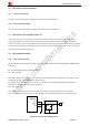
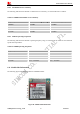

Table Of Contents
- Contents
- Version History
- 1 Introduction
- 2 SIM908 Overview
- 3 Package Information
- 4 GSM Application Interface
- 4.1 Power Supply
- 4.2 Power on/down Scenarios
- 4.3 Power Saving Mode
- 4.4 Charging Interface
- 4.5 RTC Backup
- 4.6 Serial Interfaces
- 4.7 Audio Interfaces
- 4.8 SIM Card Interface
- 4.9 LCD Display/SPI Interface
- 4.10 Keypad Interface
- 4.11 ADC
- 4.12 RI Behaviors
- 4.13 Network Status Indication
- 4.14 General Purpose Input/Output (GPIO)
- 4.15 PWM
- 4.16 I2C Bus
- 4.17 GSM Antenna Interface
- 5 GPS Application Interface
- 6 Electrical, Reliability and Radio Characteristics
- 6.1 Absolute Maximum Ratings
- 6.2 Recommended Operating Conditions
- 6.3 Digital Interface Characteristics
- 6.4 SIM Card Interface Characteristics
- 6.5 VDD_EXT Characteristics
- 6.6 SIM_VDD Characteristics
- 6.7 VRTC Characteristics
- 6.8 Current Consumption (VBAT = 3.8V, GPS engine is powered down)
- 6.9 Electro-Static Discharge
- 6.10 Radio Characteristics
- 6.11 Module label information
- Appendix

Smart Machine Smart Decision
SIM908_Hardware Design_V2.00 2012.05.07
43
In this figure, the components R101, C101 and C102 is used for antenna matching, the components’ value only
can be got after the antenna tuning. Usually, matching components’ value is provided by antenna vendor, the
default value of R101 is 0Ω, and users need to reserve the place of C101 and C102 without soldering.
The traces in bold type should be treated as 50Ω impedance controlled line in PCB layout.
5.4.2 GPS Antenna Choice Consideration
To obtain excellent GPS reception performance, a good antenna will always be required. The antenna is the most
critical item for successful GPS reception in a weak signal environment. Proper choice and placement of the
antenna will ensure that satellites at all elevations can be seen, and therefore, accurate fix measurements are
obtained.
Most customers contract with antenna design houses to properly measure the radiation pattern of the final
mounted configuration in a plastic housing with associated components near the antenna. Linear antennas are
becoming more popular, and the gain is reasonable, since a smaller ground plane can be used.
User can consider following factors as:
z Choose a linear antenna with a reasonably uniform hemispherical gain pattern of >-4dBi.
z Use of an antenna with lower gain then this will give less than desirable results. Please note that a RHCP
antenna with a gain of 3dBi, equates to a linear polarized antenna of 0dBi.
z Proper ground plane sizing is a critical consideration for small GPS antennas.
z Proper placement of the GPS antenna should always be the FIRST consideration in integrating the SIM908
GPS Module.
If the customer’s design will allow for a ceramic RHCP patch antenna with an appropriately sized ground plane,
and the patch is normally oriented towards the sky, then that particular solution usually works the best. Note that
if the patch antenna ground plane is less than 60x60mm, then compromises to the beam width and gain pattern
could result. Usually the gain becomes very directional, and looses several dB of performance. Since results can
vary, measuring the antenna radiation pattern in the final housing in an appropriate anechoic chamber is required.
Some customers do not have the size availability to implement a patch antenna approach. In that instance, use of a
Linear Polarized (LP) antenna is the next best alternative. There are new ceramic LP antennas on the market that
exhibit reasonable gain characteristics once properly mounted in the housing, and when matched to an appropriate
sized ground. Generally the ground plane requirements are smaller for a LP antenna when compared to a patch,
but once again, proper testing in an anechoic chamber is a mandatory requirement. These ceramic elements will
need to be located near the end of the ground plane, and will require several millimeters of clearance between the
closest component. It is important to note that use of a LP antenna will result in a minimum of 3dB of gain loss
when compared to a RHCP antenna at a defined elevation. This is due to the right hand gain rule of antenna
propagation.
Use of PIFA antenna is another LP possibility, but the PIFA usually exhibits a considerable amount of gain nulls,
or “holes” in the radiation pattern. This will be undesirable for obtaining a low circular error probability (CEP),
since the antenna may not allow the receiver to capture the desired satellite at the ideal orientation due to these
noted gain nulls. Once again, careful testing in an appropriate anechoic chamber is required.
If the customer’s design is for automotive applications, then an active antenna can be used and located on top of
the car in order for guarantee the best signal quality. GPS antenna choice should be based on the designing