
hardware design v2.00
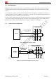
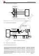
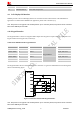
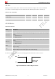
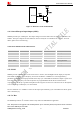
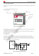
Table Of Contents
- Contents
- Version History
- 1 Introduction
- 2 SIM908 Overview
- 3 Package Information
- 4 GSM Application Interface
- 4.1 Power Supply
- 4.2 Power on/down Scenarios
- 4.3 Power Saving Mode
- 4.4 Charging Interface
- 4.5 RTC Backup
- 4.6 Serial Interfaces
- 4.7 Audio Interfaces
- 4.8 SIM Card Interface
- 4.9 LCD Display/SPI Interface
- 4.10 Keypad Interface
- 4.11 ADC
- 4.12 RI Behaviors
- 4.13 Network Status Indication
- 4.14 General Purpose Input/Output (GPIO)
- 4.15 PWM
- 4.16 I2C Bus
- 4.17 GSM Antenna Interface
- 5 GPS Application Interface
- 6 Electrical, Reliability and Radio Characteristics
- 6.1 Absolute Maximum Ratings
- 6.2 Recommended Operating Conditions
- 6.3 Digital Interface Characteristics
- 6.4 SIM Card Interface Characteristics
- 6.5 VDD_EXT Characteristics
- 6.6 SIM_VDD Characteristics
- 6.7 VRTC Characteristics
- 6.8 Current Consumption (VBAT = 3.8V, GPS engine is powered down)
- 6.9 Electro-Static Discharge
- 6.10 Radio Characteristics
- 6.11 Module label information
- Appendix

Smart Machine Smart Decision
4.17 GSM Antenna Interface
The RF interface has an impedance of 50Ω. To suit the physical design of individual applications, SIM908 offers
alternatives
z Recommended approach: GSM RF connector
z GSM_ANT pad.
SIM908_Hardware Design_V2.00 2012.05.07
40
GPS_ANT PAD
GPS
Antenna connector
GSM_ANT PAD
GSM
Antenna connector
Figure 38: The RF interface of module
If the GSM RF connector is used, the GSM_ANT pad should be left not connected, the customer’s main board
under the GSM_ANT pad should be copper keep out.
To minimize the loss on the RF cable, it need be very careful to choose RF cable. SIMCom recommends the
insertion loss should be meet following requirements:
z GSM900<1dB
z DCS1800 <1.5dB
The customer’s GSM antenna also can be located in the customer’s main board and connect to module’s
GSM_ANT pad through microstrip line or other type RF trace which impendence must be controlled in 50Ω. To
facilitate the antenna tuning and certification test, a RF connector and an antenna matching circuit should be
added. The following figure is the recommended circuit.
Figure 39: GSM antenna matching circuit