
hardware design v2.00
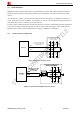
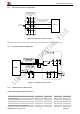
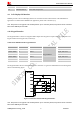
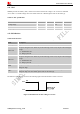
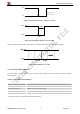
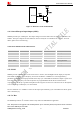
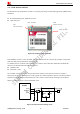
Table Of Contents
- Contents
- Version History
- 1 Introduction
- 2 SIM908 Overview
- 3 Package Information
- 4 GSM Application Interface
- 4.1 Power Supply
- 4.2 Power on/down Scenarios
- 4.3 Power Saving Mode
- 4.4 Charging Interface
- 4.5 RTC Backup
- 4.6 Serial Interfaces
- 4.7 Audio Interfaces
- 4.8 SIM Card Interface
- 4.9 LCD Display/SPI Interface
- 4.10 Keypad Interface
- 4.11 ADC
- 4.12 RI Behaviors
- 4.13 Network Status Indication
- 4.14 General Purpose Input/Output (GPIO)
- 4.15 PWM
- 4.16 I2C Bus
- 4.17 GSM Antenna Interface
- 5 GPS Application Interface
- 6 Electrical, Reliability and Radio Characteristics
- 6.1 Absolute Maximum Ratings
- 6.2 Recommended Operating Conditions
- 6.3 Digital Interface Characteristics
- 6.4 SIM Card Interface Characteristics
- 6.5 VDD_EXT Characteristics
- 6.6 SIM_VDD Characteristics
- 6.7 VRTC Characteristics
- 6.8 Current Consumption (VBAT = 3.8V, GPS engine is powered down)
- 6.9 Electro-Static Discharge
- 6.10 Radio Characteristics
- 6.11 Module label information
- Appendix

Smart Machine Smart Decision
Figure 37: Reference circuit of NETLIGHT
4.14 General Purpose Input/Output (GPIO)
SIM908 provides up to 6 GPIO pins. The output voltage level of the GPIO can be set by the AT command “AT+
SGPIO”. The input voltage level of the GPIO can also be read by the AT command “AT+ SGPIO”. For more
details, please refer to document [1].
Table 18: Pin definition of the GPIO interface
Pin name Pin number Default function Second function Default state
GPIO1/ KBR0 31 GPIO1 KBR0 Output, pull down
GPIO2/ KBR1 32 GPIO2 KBR1 Output, pull down
GPIO3/ KBR2 33 GPIO3 KBR2 Output, pull down
GPIO4/ KBC0 34 GPIO4 KBC0 Output, pull down
GPIO5/ KBC1 35 GPIO5 KBC1 Output, pull down
GPIO6/ KBC2 36 GPIO6 KBC2 Output, pull down
4.15 PWM
SIM908 provides 3 PWMs which can be used to drive a vibrator, and a backlight LED for display or keyboard.
Each PWM1 and PWM2 output frequency varies from 25.6KHz to 3.25MHz.Two 7-bit unsigned binary
parameters are used for the output period and for the duty cycle. The PWM3 for the buzzer outputs a square wave
at the desired tone frequency. The tone frequencies are programmable from 200 Hz to 5 kHz and can be
re-programmed on-the-fly to generate monophonic audio ring tones or alert tones. The tone level can be adjusted
over a 24 dB range in 4 dB steps, or it can be muted.
The AT command “AT + SPWM” is used to set the output period and duty cycle of the PWM. For details, please
refer to document [1].
4.16 I
2
C Bus
The SIM908 provides an I
2
C interface which is only used in the embedded AT application.
SIM908_Hardware Design_V2.00 2012.05.07
39
Note: This function is not supported in the standard firmware. If user wants this function, the firmware must be customized.
Please contact SIMCom for more details.