
hardware design v2.00
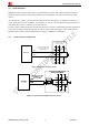
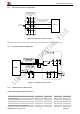
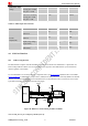
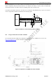
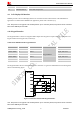
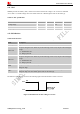
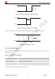
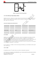
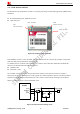
Table Of Contents
- Contents
- Version History
- 1 Introduction
- 2 SIM908 Overview
- 3 Package Information
- 4 GSM Application Interface
- 4.1 Power Supply
- 4.2 Power on/down Scenarios
- 4.3 Power Saving Mode
- 4.4 Charging Interface
- 4.5 RTC Backup
- 4.6 Serial Interfaces
- 4.7 Audio Interfaces
- 4.8 SIM Card Interface
- 4.9 LCD Display/SPI Interface
- 4.10 Keypad Interface
- 4.11 ADC
- 4.12 RI Behaviors
- 4.13 Network Status Indication
- 4.14 General Purpose Input/Output (GPIO)
- 4.15 PWM
- 4.16 I2C Bus
- 4.17 GSM Antenna Interface
- 5 GPS Application Interface
- 6 Electrical, Reliability and Radio Characteristics
- 6.1 Absolute Maximum Ratings
- 6.2 Recommended Operating Conditions
- 6.3 Digital Interface Characteristics
- 6.4 SIM Card Interface Characteristics
- 6.5 VDD_EXT Characteristics
- 6.6 SIM_VDD Characteristics
- 6.7 VRTC Characteristics
- 6.8 Current Consumption (VBAT = 3.8V, GPS engine is powered down)
- 6.9 Electro-Static Discharge
- 6.10 Radio Characteristics
- 6.11 Module label information
- Appendix

Smart Machine Smart Decision
HIGH
LOW
Idle Ring
Hang up the call
Establish the call
RI
Figure 34: RI behaviour of data calling as a receiver
Figure 35: RI behaviour of URC or receive SMS
However, if the module is used as caller, the RI will remain high. Please refer to the following figure.
Figure 36: RI behaviour as a caller
4.13 Network Status Indication
The NETLIGHT pin can be used to drive a network status indication LED. The status of this pin is listed in
following table:
Table 17: Status of the NETLIGHT pin
Status SIM908 behavior
Off SIM908 is not running
64ms On/ 800ms Off SIM908 not registered the network
64ms On/ 3000ms Off SIM908 registered to the network
64ms On/ 300ms Off PPP GPRS communication is established
A reference circuit is recommended in the following figure:
SIM908_Hardware Design_V2.00 2012.05.07
38