
hardware design v2.00
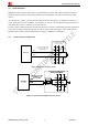
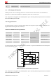
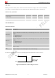
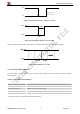
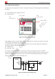
Table Of Contents
- Contents
- Version History
- 1 Introduction
- 2 SIM908 Overview
- 3 Package Information
- 4 GSM Application Interface
- 4.1 Power Supply
- 4.2 Power on/down Scenarios
- 4.3 Power Saving Mode
- 4.4 Charging Interface
- 4.5 RTC Backup
- 4.6 Serial Interfaces
- 4.7 Audio Interfaces
- 4.8 SIM Card Interface
- 4.9 LCD Display/SPI Interface
- 4.10 Keypad Interface
- 4.11 ADC
- 4.12 RI Behaviors
- 4.13 Network Status Indication
- 4.14 General Purpose Input/Output (GPIO)
- 4.15 PWM
- 4.16 I2C Bus
- 4.17 GSM Antenna Interface
- 5 GPS Application Interface
- 6 Electrical, Reliability and Radio Characteristics
- 6.1 Absolute Maximum Ratings
- 6.2 Recommended Operating Conditions
- 6.3 Digital Interface Characteristics
- 6.4 SIM Card Interface Characteristics
- 6.5 VDD_EXT Characteristics
- 6.6 SIM_VDD Characteristics
- 6.7 VRTC Characteristics
- 6.8 Current Consumption (VBAT = 3.8V, GPS engine is powered down)
- 6.9 Electro-Static Discharge
- 6.10 Radio Characteristics
- 6.11 Module label information
- Appendix

Smart Machine Smart Decision
4.11 ADC
SIM908 provides an auxiliary ADC, which can be used to measure the voltage. User can use AT command
“AT+CADC” to read the voltage value. For details of this AT command, please refer to document [1].
Table 15: ADC specification
Parameter Min Typ Max Unit
Voltage range 0 - 2.8 V
ADC Resolution - 10 - bits
Sampling rate - - 200K Hz
4.12 RI Behaviors
Table 16: RI behaviors
State RI response
Standby High
Voice call
The pin is changed to low. When any of the following events occur, the pin will be changed
to high:
(1)Establish the call
(2)Hang up the call
Data call
The pin is changed to low. When any of the following events occur, the pin will be changed
to high:
(1)Establish the call
(2)Hang up the call
The pin is changed to low, and kept low for 120ms when a SMS is received. Then it is
changed to high.
SMS
The pin is changed to low, and kept low for 120ms when some URCs are reported. Then it is
changed to high. For more details, please refer to document [8].
URC
The behavior of the RI pin is shown in the following figure when the module is used as a receiver.
Figure 33: RI behaviour of voice calling as a receiver
SIM908_Hardware Design_V2.00 2012.05.07
37