
hardware design v2.00
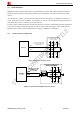
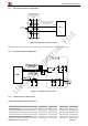
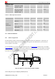
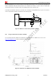
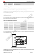
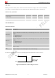
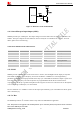
Table Of Contents
- Contents
- Version History
- 1 Introduction
- 2 SIM908 Overview
- 3 Package Information
- 4 GSM Application Interface
- 4.1 Power Supply
- 4.2 Power on/down Scenarios
- 4.3 Power Saving Mode
- 4.4 Charging Interface
- 4.5 RTC Backup
- 4.6 Serial Interfaces
- 4.7 Audio Interfaces
- 4.8 SIM Card Interface
- 4.9 LCD Display/SPI Interface
- 4.10 Keypad Interface
- 4.11 ADC
- 4.12 RI Behaviors
- 4.13 Network Status Indication
- 4.14 General Purpose Input/Output (GPIO)
- 4.15 PWM
- 4.16 I2C Bus
- 4.17 GSM Antenna Interface
- 5 GPS Application Interface
- 6 Electrical, Reliability and Radio Characteristics
- 6.1 Absolute Maximum Ratings
- 6.2 Recommended Operating Conditions
- 6.3 Digital Interface Characteristics
- 6.4 SIM Card Interface Characteristics
- 6.5 VDD_EXT Characteristics
- 6.6 SIM_VDD Characteristics
- 6.7 VRTC Characteristics
- 6.8 Current Consumption (VBAT = 3.8V, GPS engine is powered down)
- 6.9 Electro-Static Discharge
- 6.10 Radio Characteristics
- 6.11 Module label information
- Appendix

Smart Machine Smart Decision
Table 12: Pin description (Amphenol SIM card holder)
Pin name Signal Description
C1 SIM-VDD SIM card power supply
C2 SIM-RST SIM card reset
C3 SIM-CLK SIM card clock
C5 GND Connect to GND
C6 VPP Not connect
C7 SIM-DATA SIM card data I/O
For 8 pins SIM card holder, SIMCom recommends to use Molex 91228.User can visit http://www.molex.com for
more information about the holder.
Figure 31: Molex 91228 SIM card holder
Table 13: Pin description (Molex SIM card holder)
Pin name Signal Description
C1 SIM-VDD SIM card power supply
C2 SIM-RST SIM card reset
C3 SIM-CLK SIM card clock
C4 GND Connect to GND
C5 GND Connect to GND
C6 VPP Not connect
SIM908_Hardware Design_V2.00 2012.05.07
35