
hardware design v2.00
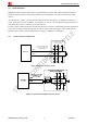
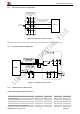
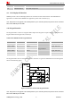
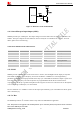
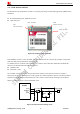
Table Of Contents
- Contents
- Version History
- 1 Introduction
- 2 SIM908 Overview
- 3 Package Information
- 4 GSM Application Interface
- 4.1 Power Supply
- 4.2 Power on/down Scenarios
- 4.3 Power Saving Mode
- 4.4 Charging Interface
- 4.5 RTC Backup
- 4.6 Serial Interfaces
- 4.7 Audio Interfaces
- 4.8 SIM Card Interface
- 4.9 LCD Display/SPI Interface
- 4.10 Keypad Interface
- 4.11 ADC
- 4.12 RI Behaviors
- 4.13 Network Status Indication
- 4.14 General Purpose Input/Output (GPIO)
- 4.15 PWM
- 4.16 I2C Bus
- 4.17 GSM Antenna Interface
- 5 GPS Application Interface
- 6 Electrical, Reliability and Radio Characteristics
- 6.1 Absolute Maximum Ratings
- 6.2 Recommended Operating Conditions
- 6.3 Digital Interface Characteristics
- 6.4 SIM Card Interface Characteristics
- 6.5 VDD_EXT Characteristics
- 6.6 SIM_VDD Characteristics
- 6.7 VRTC Characteristics
- 6.8 Current Consumption (VBAT = 3.8V, GPS engine is powered down)
- 6.9 Electro-Static Discharge
- 6.10 Radio Characteristics
- 6.11 Module label information
- Appendix

Smart Machine Smart Decision
THD <1% at F=1KHz;
pre-amp gain = 20 dB;
PGA gain = 14 dB
15.9
SIM908_Hardware Design_V2.00 2012.05.07
33
mVrms Differential input
voltage
THD <5% at F=1KHz;
pre-amp gain = 0 dB;
PGA gain = 0 dB
740 mVrms
Table 11: Audio output characteristics
Parameter Conditions Min Typ Max Unit
RL=32Ω
THD=0.1%
- 91 - mW
RL=32Ω
THD=1%
- 96 - mW
Output swing voltage
(single ended)
1.1 Vpp
Normal
Output(SPK)
Output swing voltage
(differential)
2.2 Vpp
4.8 SIM Card Interface
4.8.1 SIM Card Application
The SIM interface complies with the GSM Phase 1 specification and the new GSM Phase 2+ specification for
FAST 64 kbps SIM card. Both 1.8V and 3.0V SIM card are supported. The SIM interface is powered from an
internal regulator in the module.
It is recommended to use an ESD protection component such as ST (www.st.com
) ESDA6V1W5 or ON SEMI
(www.onsemi.com
) SMF05C.The pull up resistor (15KΩ) on the SIM_DATA line is already added in the module
internal. Note that the SIM peripheral circuit should be close to the SIM card socket. The reference circuit of the
8-pin SIM card holder is illustrated in the following figure.
Figure 28: Reference circuit of the 8-pin SIM card holder
Note: The SIM_Presence pin is multiplexing with KBC0 (PIN 34).