
hardware design v2.00
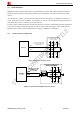
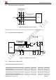
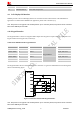
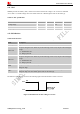
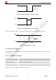
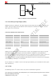
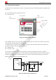
Table Of Contents
- Contents
- Version History
- 1 Introduction
- 2 SIM908 Overview
- 3 Package Information
- 4 GSM Application Interface
- 4.1 Power Supply
- 4.2 Power on/down Scenarios
- 4.3 Power Saving Mode
- 4.4 Charging Interface
- 4.5 RTC Backup
- 4.6 Serial Interfaces
- 4.7 Audio Interfaces
- 4.8 SIM Card Interface
- 4.9 LCD Display/SPI Interface
- 4.10 Keypad Interface
- 4.11 ADC
- 4.12 RI Behaviors
- 4.13 Network Status Indication
- 4.14 General Purpose Input/Output (GPIO)
- 4.15 PWM
- 4.16 I2C Bus
- 4.17 GSM Antenna Interface
- 5 GPS Application Interface
- 6 Electrical, Reliability and Radio Characteristics
- 6.1 Absolute Maximum Ratings
- 6.2 Recommended Operating Conditions
- 6.3 Digital Interface Characteristics
- 6.4 SIM Card Interface Characteristics
- 6.5 VDD_EXT Characteristics
- 6.6 SIM_VDD Characteristics
- 6.7 VRTC Characteristics
- 6.8 Current Consumption (VBAT = 3.8V, GPS engine is powered down)
- 6.9 Electro-Static Discharge
- 6.10 Radio Characteristics
- 6.11 Module label information
- Appendix

Smart Machine Smart Decision
4.7.2 Microphone Interfaces Configuration
10pF
33pF
33pF
33pF
SIM908_Hardware Design_V2.00 2012.05.07
32
MIC1P
MIC1N
Electret
Microphone
10pF
10pF
ESD
ANTI
ESD
ANTI
The lines in bold type should
be accorded to differential
signal layout rules
These components
should be placed to
microphone as close as
possible
MODULE
Figure 26 : Microphone reference circuit
Microphone input also could be used to LINE-IN input. For details, please refer to document [6].
4.7.3 Earphone Interface Configuration
Figure 27: Earphone reference circuit
4.7.4 Audio Electronic Characteristics
Table 10: Microphone input characteristics
Parameter Min Typ Max Unit
Working Voltage 1.2 1.5 2.0 V
Working Current 200 500 uA
External Microphone Load Resistance 1.2 2.2 kΩ
Internal biasing DC Characteristics 2.5 V