
hardware design v2.00
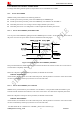
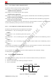
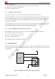
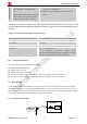
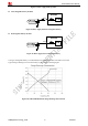
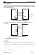
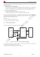
Table Of Contents
- Contents
- Version History
- 1 Introduction
- 2 SIM908 Overview
- 3 Package Information
- 4 GSM Application Interface
- 4.1 Power Supply
- 4.2 Power on/down Scenarios
- 4.3 Power Saving Mode
- 4.4 Charging Interface
- 4.5 RTC Backup
- 4.6 Serial Interfaces
- 4.7 Audio Interfaces
- 4.8 SIM Card Interface
- 4.9 LCD Display/SPI Interface
- 4.10 Keypad Interface
- 4.11 ADC
- 4.12 RI Behaviors
- 4.13 Network Status Indication
- 4.14 General Purpose Input/Output (GPIO)
- 4.15 PWM
- 4.16 I2C Bus
- 4.17 GSM Antenna Interface
- 5 GPS Application Interface
- 6 Electrical, Reliability and Radio Characteristics
- 6.1 Absolute Maximum Ratings
- 6.2 Recommended Operating Conditions
- 6.3 Digital Interface Characteristics
- 6.4 SIM Card Interface Characteristics
- 6.5 VDD_EXT Characteristics
- 6.6 SIM_VDD Characteristics
- 6.7 VRTC Characteristics
- 6.8 Current Consumption (VBAT = 3.8V, GPS engine is powered down)
- 6.9 Electro-Static Discharge
- 6.10 Radio Characteristics
- 6.11 Module label information
- Appendix

Smart Machine Smart Decision
Charge-only Mode
Connect charger to module’s VCHG Pin
while SIM908 is in POWER DOWN
mode.
IMPORTANT: Here Charge-only mode is
charging when power is down, it means
that not all software tasks are running.
z Battery can be charged when GSM engine is not
registered to GSM network;
z Only a few AT commands is available, as listed
below.
Note: VBAT can not provide more than 5mA current while SIM908 module is during the DDLO charge state. In other words it is
strongly recommended that VBAT should not be the main power supply in the application subsystem if SIM908 DDLO charging
state occurs.
Table 9: AT command usually used in Charge-only mode
AT command Function
AT+CCLK Set data and time of RTC
AT+ CP OW D Power down
AT+CBC Indicated charge state and voltage
AT+CFUN Start or close the protocol
Set AT command “AT+CFUN=1”, module can be
transferred from Charge-only mode to Charging in normal
mode. In Charge-only mode, the default value is 0.
4.4.5 Charger Requirements
Following is the requirements of charger for SIM908:
z Simple transformer power plug
z Output voltage: 5.0V~6V
z Minimum supply current: 750mA
z A 10V peak voltage is allowed for maximum 1ms when charging current is switched off.
z A 1.6A peak current is allowed for maximum 1ms when charging current is switched on.
4.5 RTC Backup
Current input for RTC when the VBAT is not supplied for the system. Current output for backup battery when
the VBAT power supply is in present and the backup battery is in low voltage state. The RTC power supply of
module can be provided by an external capacitor or a battery (non-chargeable or rechargeable) through the VRTC.
The following figures show various reference circuits for RTC back up.
z External capacitor for RTC
SIM908_Hardware Design_V2.00 2012.05.07
27