
hardware design v2.00
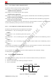
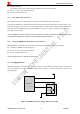
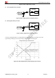
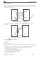
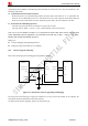
Table Of Contents
- Contents
- Version History
- 1 Introduction
- 2 SIM908 Overview
- 3 Package Information
- 4 GSM Application Interface
- 4.1 Power Supply
- 4.2 Power on/down Scenarios
- 4.3 Power Saving Mode
- 4.4 Charging Interface
- 4.5 RTC Backup
- 4.6 Serial Interfaces
- 4.7 Audio Interfaces
- 4.8 SIM Card Interface
- 4.9 LCD Display/SPI Interface
- 4.10 Keypad Interface
- 4.11 ADC
- 4.12 RI Behaviors
- 4.13 Network Status Indication
- 4.14 General Purpose Input/Output (GPIO)
- 4.15 PWM
- 4.16 I2C Bus
- 4.17 GSM Antenna Interface
- 5 GPS Application Interface
- 6 Electrical, Reliability and Radio Characteristics
- 6.1 Absolute Maximum Ratings
- 6.2 Recommended Operating Conditions
- 6.3 Digital Interface Characteristics
- 6.4 SIM Card Interface Characteristics
- 6.5 VDD_EXT Characteristics
- 6.6 SIM_VDD Characteristics
- 6.7 VRTC Characteristics
- 6.8 Current Consumption (VBAT = 3.8V, GPS engine is powered down)
- 6.9 Electro-Static Discharge
- 6.10 Radio Characteristics
- 6.11 Module label information
- Appendix

Smart Machine Smart Decision
z Pull down DTR pin.
The serial port will be active after DTR pin is pulled to low level for about 50ms.
z Receive a voice or data call from network.
z Receive a SMS from network.
4.3.4 Sleep Mode 2 (AT+CSCLK=2)
Be sure that GPS function is closed, then AT+CSCLK=2 can set module to the sleep mode 2.
In this mode, SIM908 will continuously monitor the serial port data signal. When there is no data transfer over 5
seconds on the RXD signal and there is no on air and hardware interrupts (such as GPIO interrupt), SIM908 will
enter sleep mode 2 automatically. In this mode, SIM908 can still receive paging or SMS from network but the
serial port is not accessible.
Note: For SIM908, It is requested to set AT command “AT+CSCLK=2” to enable the sleep mode 2; the default value is 0, which
can not make the module to enter sleep mode. For more details please refer to document [1].
4.3.5 Wake Up SIM908 from Sleep Mode 2 (AT+CSCLK=2)
When SIM908 is in sleep mode 2 (AT+CSCLK=2), the following methods can wake up the module:
z Send data to SIM908 via main serial port.
*
z Receive a voice or data call from network.
z Receive a SMS from network.
Note: The first byte of the user’s data will not be recognized.
4.4 Charging Interface
SIM908 has integrated a charging circuit inside the module for Li-Ion batteries charging control, which make it
very convenient for user’s applications that support battery charging. A common connection is shown in the
following figure:
Module
Battery Pack
R
TEMP
Thermistor
TEMP_BAT
V
BAT
V
CHG
5V
Figure 16: SIM908 with battery charger and pack connection
SIM908_Hardware Design_V2.00 2012.05.07
24