
hardware design v2.00
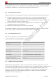
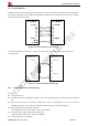
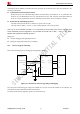
Table Of Contents
- Contents
- Version History
- 1 Introduction
- 2 SIM908 Overview
- 3 Package Information
- 4 GSM Application Interface
- 4.1 Power Supply
- 4.2 Power on/down Scenarios
- 4.3 Power Saving Mode
- 4.4 Charging Interface
- 4.5 RTC Backup
- 4.6 Serial Interfaces
- 4.7 Audio Interfaces
- 4.8 SIM Card Interface
- 4.9 LCD Display/SPI Interface
- 4.10 Keypad Interface
- 4.11 ADC
- 4.12 RI Behaviors
- 4.13 Network Status Indication
- 4.14 General Purpose Input/Output (GPIO)
- 4.15 PWM
- 4.16 I2C Bus
- 4.17 GSM Antenna Interface
- 5 GPS Application Interface
- 6 Electrical, Reliability and Radio Characteristics
- 6.1 Absolute Maximum Ratings
- 6.2 Recommended Operating Conditions
- 6.3 Digital Interface Characteristics
- 6.4 SIM Card Interface Characteristics
- 6.5 VDD_EXT Characteristics
- 6.6 SIM_VDD Characteristics
- 6.7 VRTC Characteristics
- 6.8 Current Consumption (VBAT = 3.8V, GPS engine is powered down)
- 6.9 Electro-Static Discharge
- 6.10 Radio Characteristics
- 6.11 Module label information
- Appendix

Smart Machine Smart Decision
SIM908_Hardware Design_V2.00 2012.05.07
23
4.3 Power Saving Mode
SIM908 have two sleep modes: sleep mode 1 is enabled by hardware pin DTR; sleep mode 2 is only enabled by
serial port regardless of the DTR. In sleep mode, the current of module is very low. The AT command
“AT+CFUN=<fun>” can be used to set SIM908 into minimum functionality. When SIM908 is in sleep mode and
minimum functionality, the current of module is lowest.
Note: Customer must shut off the power supply of GPS, and then the AT commands about the power saving mode can be
executed correctly, and the current consumption will be lower.
4.3.1 Minimum Functionality Mode
There are three functionality modes, which could be set by the AT command “AT+CFUN=<fun>”. The command
provides the choice of the functionality levels <fun>=0,1,4.
z AT+CFUN=0: minimum functionality.
z AT+CFUN=1: full functionality (default).
z AT+CFUN=4: flight mode (disable RF function).
Minimum functionality mode minimizes the current consumption to the lowest level. If SIM908 is set to
minimum functionality by “AT+CFUN=0”, the RF function and SIM card function will be disabled. In this case,
the serial port is still accessible, but all AT commands correlative with RF function and SIM card function will not
be accessible.
For detailed information about the AT Command “AT+CFUN=<fun>”, please refer to document [1].
Table 6: The current consumption of Minimum Functionality Mode
<fun> Current consumption(uA) (sleep mode)
0 651
1 1500
4 715
4.3.2 Sleep Mode 1 (AT+CSCLK=1)
When the GPS function is shut off, user can control SIM908 module to enter or exit the sleep mode 1
(AT+CSCLK=1) by DTR signal. When DTR is in high level and without interrupt (on air and hardware such as
GPIO interrupt or data in serial port), SIM908 will enter sleep mode 1 automatically. In this mode, SIM908 can
still receive paging or SMS from network but the serial port is not accessible.
Note: For SIM908, it requests to set AT command “AT+CSCLK=1” and ensure DTR at high level to enable the sleep mode 1; the
default value is 0, which can not make the module to enter sleep mode. For more details please refer to document [1].
4.3.3 Wake Up SIM908 from Sleep Mode 1 (AT+CSCLK=1)
When SIM908 is in sleep mode 1 (AT+CSCLK=1), the following methods can wake up the module: