
hardware design v2.00
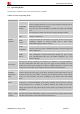
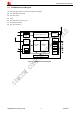
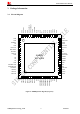
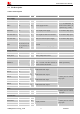
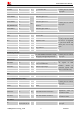
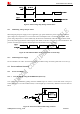
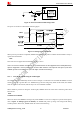
Table Of Contents
- Contents
- Version History
- 1 Introduction
- 2 SIM908 Overview
- 3 Package Information
- 4 GSM Application Interface
- 4.1 Power Supply
- 4.2 Power on/down Scenarios
- 4.3 Power Saving Mode
- 4.4 Charging Interface
- 4.5 RTC Backup
- 4.6 Serial Interfaces
- 4.7 Audio Interfaces
- 4.8 SIM Card Interface
- 4.9 LCD Display/SPI Interface
- 4.10 Keypad Interface
- 4.11 ADC
- 4.12 RI Behaviors
- 4.13 Network Status Indication
- 4.14 General Purpose Input/Output (GPIO)
- 4.15 PWM
- 4.16 I2C Bus
- 4.17 GSM Antenna Interface
- 5 GPS Application Interface
- 6 Electrical, Reliability and Radio Characteristics
- 6.1 Absolute Maximum Ratings
- 6.2 Recommended Operating Conditions
- 6.3 Digital Interface Characteristics
- 6.4 SIM Card Interface Characteristics
- 6.5 VDD_EXT Characteristics
- 6.6 SIM_VDD Characteristics
- 6.7 VRTC Characteristics
- 6.8 Current Consumption (VBAT = 3.8V, GPS engine is powered down)
- 6.9 Electro-Static Discharge
- 6.10 Radio Characteristics
- 6.11 Module label information
- Appendix

Smart Machine Smart Decision
SIM908_Hardware Design_V2.00 2012.05.07
14
3.2 Pin Description
Table 5: Pin description
Pin name Pin number I/O Description Comment
Power supply
VBAT 62, 63 I Power supply 3.2V ~ 4.8V
VRTC 42 I/O Power supply for RTC
It is recommended to
connect with a battery or
a capacitor (e.g. 4.7uF).
VDD-EXT 44 O 2.8V output power supply If it is unused, keep open.
GPS-VANT-OUT 75 O 2.8V output for GPS active antenna If it is unused, keep open.
GPS-VANT-IN 76 I GPS active antenna power supply If it is unused, keep open.
GND
1, 2, 5, 10, 14, 37,
40, 41, 43, 57, 58,
60, 61, 64, 65, 77,
78, 80
Ground
Charge interface
VCHG 74 I Charger input
TEMP_BAT 73 I Battery temperature sensor
Power on/down
PWRKEY 3 I
PWRKEY should be pulled low at
least 1 second and then released to
power on/down the module.
Pulled up internally.
Audio interfaces
MIC1P 23
MIC1N 24
I Differential audio input
SPK1P 22
SPK1N 21
O Differential audio output
MIC2P 27
MIC2N 28
I Differential audio input
SPK2N 25
SPK2P 26
O Differential audio output
If these pins are unused,
keep open.
Status
STATUS 52 O Power on status
NETLIGHT 51 O Network status
If these pins are unused,
keep open.
LCD interface
DISP -CLK 6 O
DISP-DATA 7 I/O
DISP -D/C 8 O
DISP -CS 9 O
Display interface
If these pins are unused,
keep open.