
Sim800 hardware design v1.05
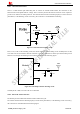
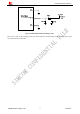
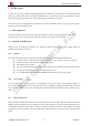
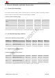
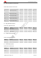
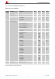
Table Of Contents
- Version History
- 1. Introduction
- 2. SIM800 Overview
- 3. Package Information
- 4. Application Interface
- 4.1. Power Supply
- 4.2. Power on/down SIM800
- 4.3. Power Saving Mode
- 4.4. RTC Backup
- 4.5. Serial Port and USB Interface
- 4.6. RI Behaviors
- 4.7. Audio Interfaces
- 4.8. Bluetooth
- 4.9. SIM Card Interface
- 4.10. PCM Interface
- 4.11. Keypad Interface
- 4.12. I2C BUS
- 4.13. General Purpose Input/Output (GPIO)
- 4.14. ADC
- 4.15. PWM
- 4.16. Network Status Indication
- 4.17. Operating Status Indication
- 4.18. KPLED
- 4.19. RF Synchronization Signal
- 4.20. Antenna Interface
- 5. PCB Layout
- 6. Electrical, Reliability and Radio Characteristics
- 6.1 Absolute Maximum Ratings
- 6.2 Recommended Operating Conditions
- 6.3 Digital Interface Characteristics
- 6.4 SIM Card Interface Characteristics
- 6.5 SIM_VDD Characteristics
- 6.6 VDD_EXT Characteristics
- 6.7 VRTC Characteristics
- 6.8 Current Consumption (VBAT=4V)
- 6.9 Electro-Static Discharge
- 6.10 Radio Characteristics
- 6.11 Module RF Receive Sensitivity
- 6.12 Module Operating Frequencies
- 7. Manufacturing
- 8. Appendix

Smart Machine Smart Decision
4.20.1. GSM Antenna Interface
There is a GSM antenna pad named RF_ANT to connect an external GSM antenna, the connection of the
antenna must be decoupled from DC voltage. This is necessary because the antenna connector is DC coupled to
ground via an inductor for ESD protection. The external antenna must be matched properly to achieve the best
performance, so the matching circuit is necessary, the connection is recommended as following:
Figure 47: GSM antenna matching circuit
R101, C101, C102 are the matching circuit, the values depend on antenna debug result. Normally R101 is 0,
C101 and C102 are not mounted. The RF connector is used for conducted test. If the space between RF pin and
antenna is not enough, the matching circuit could be simplified as the following figure:
GN
D
SIM800_Hardware Design_V1.05 52 2014-03-25
R101
C101
C102
GSM
Antenna
Module
RF_ANT
GN
D
Figure 48: GSM simple antenna matching circuit
Normally R101 is 0; C101 and C102 are not mounted.
4.20.2. Bluetooth Antenna Interface
The module provides a Bluetooth antenna interface named ANT_BT.
The external antenna must be matched properly to achieve best performance, so the matching circuit is necessary,
the connection is recommended as the following figure: