
Sim800 hardware design v1.05
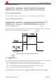
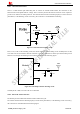
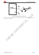
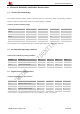
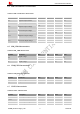
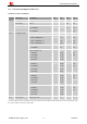
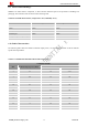
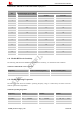
Table Of Contents
- Version History
- 1. Introduction
- 2. SIM800 Overview
- 3. Package Information
- 4. Application Interface
- 4.1. Power Supply
- 4.2. Power on/down SIM800
- 4.3. Power Saving Mode
- 4.4. RTC Backup
- 4.5. Serial Port and USB Interface
- 4.6. RI Behaviors
- 4.7. Audio Interfaces
- 4.8. Bluetooth
- 4.9. SIM Card Interface
- 4.10. PCM Interface
- 4.11. Keypad Interface
- 4.12. I2C BUS
- 4.13. General Purpose Input/Output (GPIO)
- 4.14. ADC
- 4.15. PWM
- 4.16. Network Status Indication
- 4.17. Operating Status Indication
- 4.18. KPLED
- 4.19. RF Synchronization Signal
- 4.20. Antenna Interface
- 5. PCB Layout
- 6. Electrical, Reliability and Radio Characteristics
- 6.1 Absolute Maximum Ratings
- 6.2 Recommended Operating Conditions
- 6.3 Digital Interface Characteristics
- 6.4 SIM Card Interface Characteristics
- 6.5 SIM_VDD Characteristics
- 6.6 VDD_EXT Characteristics
- 6.7 VRTC Characteristics
- 6.8 Current Consumption (VBAT=4V)
- 6.9 Electro-Static Discharge
- 6.10 Radio Characteristics
- 6.11 Module RF Receive Sensitivity
- 6.12 Module Operating Frequencies
- 7. Manufacturing
- 8. Appendix

Smart Machine Smart Decision
Table 36: KPLED specification
Pin name Min Typ Max Unit
KPLED 60 - 100 mA
SIM800_Hardware Design_V1.05 51 2014-03-25
4.19. RF Synchronization Signal
The synchronization signal serves to indicate growing power consumption during the transmit burst.
Table 37: Definition of the RF_SYNC pin
Pin name Pin number Description
RF_SYNC 67 Transmit synchronization signal
Note: Do not pull up RF_SYNC.
The timing of the synchronization signal is shown in the following figure. High level of the RF_SYNC signal
indicates increased power consumption during transmission.
Figure 46: RF_SYNC signal during transmit burst
4.20. Antenna Interface
There are two antenna ports for SIM800, GSM antenna port named RF_ANT and Bluetooth antenna port named
ANT_BT; The RF interfaces of the two antenna ports both have the impedance of 50
z The input impendence of the antenna should be 50, and the VSWR should be less than 2.
z It is recommended that GSM antenna and Bluetooth antenna be placed as far as better.
z The isolations of the two antenna should be more than 30db
NOTE: About the RF trace layout please refer to
《
AN_SMT Module_RF_Reference Design_Guide
》