
Sim800 hardware design v1.05
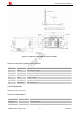
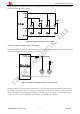

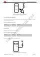
Table Of Contents
- Version History
- 1. Introduction
- 2. SIM800 Overview
- 3. Package Information
- 4. Application Interface
- 4.1. Power Supply
- 4.2. Power on/down SIM800
- 4.3. Power Saving Mode
- 4.4. RTC Backup
- 4.5. Serial Port and USB Interface
- 4.6. RI Behaviors
- 4.7. Audio Interfaces
- 4.8. Bluetooth
- 4.9. SIM Card Interface
- 4.10. PCM Interface
- 4.11. Keypad Interface
- 4.12. I2C BUS
- 4.13. General Purpose Input/Output (GPIO)
- 4.14. ADC
- 4.15. PWM
- 4.16. Network Status Indication
- 4.17. Operating Status Indication
- 4.18. KPLED
- 4.19. RF Synchronization Signal
- 4.20. Antenna Interface
- 5. PCB Layout
- 6. Electrical, Reliability and Radio Characteristics
- 6.1 Absolute Maximum Ratings
- 6.2 Recommended Operating Conditions
- 6.3 Digital Interface Characteristics
- 6.4 SIM Card Interface Characteristics
- 6.5 SIM_VDD Characteristics
- 6.6 VDD_EXT Characteristics
- 6.7 VRTC Characteristics
- 6.8 Current Consumption (VBAT=4V)
- 6.9 Electro-Static Discharge
- 6.10 Radio Characteristics
- 6.11 Module RF Receive Sensitivity
- 6.12 Module Operating Frequencies
- 7. Manufacturing
- 8. Appendix

Smart Machine Smart Decision
4.7K
47K
VBAT
PWM
Figure 43: Reference circuit of PWM drive buzzer
Table 30: Buzzer output characteristics
Parameter Min Typ Max Unit
Working voltage 2.5 2.8 2.9 V
Working current 16 mA
Note: PWM pin must keep low when module in the boot process.
Table 31: PWM multiplex function
Pin name Pin number Mode 0(default) Mode 1
PWM1/GPIO22 35 PWM1 GPIO22
PWM2/GPIO23 36 GPIO23 PWM2
SIM800_Hardware Design_V1.05 49 2014-03-25
4.16. Network Status Indication
Table 32: Pin definition of the NETLIGHT
Pin name Pin number Description
NETLIGHT 52
Network Status Indication
The NETLIGHT pin can be used to drive a network status indication LED. The status of this pin is listed in
following table:
Table 33: Status of the NETLIGHT pin
Status SIM800 behavior
Off SIM800 is not running
64ms On/ 800ms Off SIM800 not registered the network
64ms On/ 3000ms Off SIM800 registered to the network
64ms On/ 300ms Off GPRS communication is established
Reference circuit is recommended in the following figure: