
Sim800 hardware design v1.05
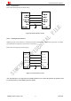
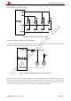
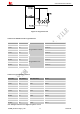

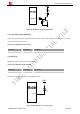
Table Of Contents
- Version History
- 1. Introduction
- 2. SIM800 Overview
- 3. Package Information
- 4. Application Interface
- 4.1. Power Supply
- 4.2. Power on/down SIM800
- 4.3. Power Saving Mode
- 4.4. RTC Backup
- 4.5. Serial Port and USB Interface
- 4.6. RI Behaviors
- 4.7. Audio Interfaces
- 4.8. Bluetooth
- 4.9. SIM Card Interface
- 4.10. PCM Interface
- 4.11. Keypad Interface
- 4.12. I2C BUS
- 4.13. General Purpose Input/Output (GPIO)
- 4.14. ADC
- 4.15. PWM
- 4.16. Network Status Indication
- 4.17. Operating Status Indication
- 4.18. KPLED
- 4.19. RF Synchronization Signal
- 4.20. Antenna Interface
- 5. PCB Layout
- 6. Electrical, Reliability and Radio Characteristics
- 6.1 Absolute Maximum Ratings
- 6.2 Recommended Operating Conditions
- 6.3 Digital Interface Characteristics
- 6.4 SIM Card Interface Characteristics
- 6.5 SIM_VDD Characteristics
- 6.6 VDD_EXT Characteristics
- 6.7 VRTC Characteristics
- 6.8 Current Consumption (VBAT=4V)
- 6.9 Electro-Static Discharge
- 6.10 Radio Characteristics
- 6.11 Module RF Receive Sensitivity
- 6.12 Module Operating Frequencies
- 7. Manufacturing
- 8. Appendix

Smart Machine Smart Decision
4.14. ADC
Table 27: Pin definition of the ADC
Pin name Pin number Description
ADC 25 Analog to Digital Converter
SIM800_Hardware Design_V1.05 48 2014-03-25
SIM800 provides an auxiliary ADC, which can be used to measure the voltage. User can use AT command
“AT+CADC” to read the voltage value. For details of this AT command, please refer to document [1].
Table 28: ADC specification
Parameter Min Typ Max Unit
Voltage range 0 - 2.8 V
ADC Resolution - 10 - bits
Sampling rate - - 1.0833 MHz
ADC precision 10 20 mV
Note: the voltage should less than 2.8V, or the ADC may be damaged.
4.15. PWM
Table 29: Pin definition of the PWM
Pin name
Pin number Description
PWM1/GPIO22 35 PWM1, multiplex with GPIO22
PWM2/GPIO23 36 PWM2, multiplex with GPIO23
Note: SIM800 can only support 1 PWM synchronously, if customer set PIN 35 as PWM, so PIN36 can only be
used as GPIO.
PWM output frequency varies from 0 to 2KHz.Two 7-bit unsigned binary parameters are used for the output
period and for the duty cycle. The AT command “AT + SPWM” is used to set the output period and duty cycle of
the PWM. For details, please refer to document [1].
A typical circuit of the PWM drives buzzer is shown in the following figure: