
Sim800 hardware design v1.05
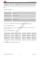
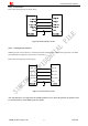
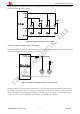
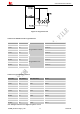

Table Of Contents
- Version History
- 1. Introduction
- 2. SIM800 Overview
- 3. Package Information
- 4. Application Interface
- 4.1. Power Supply
- 4.2. Power on/down SIM800
- 4.3. Power Saving Mode
- 4.4. RTC Backup
- 4.5. Serial Port and USB Interface
- 4.6. RI Behaviors
- 4.7. Audio Interfaces
- 4.8. Bluetooth
- 4.9. SIM Card Interface
- 4.10. PCM Interface
- 4.11. Keypad Interface
- 4.12. I2C BUS
- 4.13. General Purpose Input/Output (GPIO)
- 4.14. ADC
- 4.15. PWM
- 4.16. Network Status Indication
- 4.17. Operating Status Indication
- 4.18. KPLED
- 4.19. RF Synchronization Signal
- 4.20. Antenna Interface
- 5. PCB Layout
- 6. Electrical, Reliability and Radio Characteristics
- 6.1 Absolute Maximum Ratings
- 6.2 Recommended Operating Conditions
- 6.3 Digital Interface Characteristics
- 6.4 SIM Card Interface Characteristics
- 6.5 SIM_VDD Characteristics
- 6.6 VDD_EXT Characteristics
- 6.7 VRTC Characteristics
- 6.8 Current Consumption (VBAT=4V)
- 6.9 Electro-Static Discharge
- 6.10 Radio Characteristics
- 6.11 Module RF Receive Sensitivity
- 6.12 Module Operating Frequencies
- 7. Manufacturing
- 8. Appendix

Smart Machine Smart Decision
4.12. I2C BUS
The SIM800 provides an I2C interface, it can be driven by either the master or slave and conform to the I2C
specification. It has the following features:
z Compliant master mode operation
z Adjustable clock speed for LS/FS mode operation
z Support 7-bit/10-bit addressing
z Support high speed mode
z Support slave clock extension
z START/STOP/REPEATED condition
z Manual transfer mode
z Multi-write per transfer (up to 8 data bytes for non-DMA mode)
z Multi-read per transfer (up to 8 data bytes for non-DMA mode)
z Multi-transfer per transaction
z Combined format transfer with length change capability
z Active drive/write-and I/O configuration
Table 24: Pin definition of the I2C
Pin name Pin number Description
SCL 37 I2C serial bus clock
SDA 38 I2C serial bus data
Note: I2C has been pulled up to 2.8V via 4.7KΩ.
Table 25: I2C multiplex function
Pin name Pin number Mode 0(default) Mode 1
SCL 37 SCL GPIO24
SDA 38 SDA GPIO25
4.13. General Purpose Input/Output (GPIO)
SIM800 provides 2 GPIO pins. The output voltage level of the GPIO can be set by the AT command “AT+
SGPIO”. The input voltage level of the GPIO can also be read by the AT command “AT+ SGPIO”. For more
details, please refer to document [1].
Table 26: Pin definition of the GPIO
Pin name Pin number
Reset state
GPIO17
11 Pull down
GPIO19
13 Pull down
SIM800_Hardware Design_V1.05 47 2014-03-25