
Sim800 hardware design v1.05
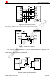
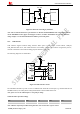
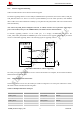
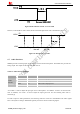
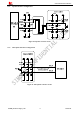
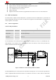
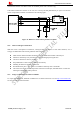
Table Of Contents
- Version History
- 1. Introduction
- 2. SIM800 Overview
- 3. Package Information
- 4. Application Interface
- 4.1. Power Supply
- 4.2. Power on/down SIM800
- 4.3. Power Saving Mode
- 4.4. RTC Backup
- 4.5. Serial Port and USB Interface
- 4.6. RI Behaviors
- 4.7. Audio Interfaces
- 4.8. Bluetooth
- 4.9. SIM Card Interface
- 4.10. PCM Interface
- 4.11. Keypad Interface
- 4.12. I2C BUS
- 4.13. General Purpose Input/Output (GPIO)
- 4.14. ADC
- 4.15. PWM
- 4.16. Network Status Indication
- 4.17. Operating Status Indication
- 4.18. KPLED
- 4.19. RF Synchronization Signal
- 4.20. Antenna Interface
- 5. PCB Layout
- 6. Electrical, Reliability and Radio Characteristics
- 6.1 Absolute Maximum Ratings
- 6.2 Recommended Operating Conditions
- 6.3 Digital Interface Characteristics
- 6.4 SIM Card Interface Characteristics
- 6.5 SIM_VDD Characteristics
- 6.6 VDD_EXT Characteristics
- 6.7 VRTC Characteristics
- 6.8 Current Consumption (VBAT=4V)
- 6.9 Electro-Static Discharge
- 6.10 Radio Characteristics
- 6.11 Module RF Receive Sensitivity
- 6.12 Module Operating Frequencies
- 7. Manufacturing
- 8. Appendix

Smart Machine Smart Decision
z Fully compliant with Bluetooth specification3.0 + EDR
z Support operation with GPS and GSM/GPRS worldwide radio systems
z Fully integrated PA provides 10dbm output power
z Up to 4 simultaneous active ACL links
z Support sniff mode
z Supports PCM interface and built-in programmable transcoders for liner voice with transmission
4.9. SIM Card Interface
The SIM interface complies with the GSM Phase 1 specification and the new GSM Phase 2+ specification for
FAST 64 kbps SIM card. Both 1.8V and 3.0V SIM card are supported. The SIM interface is powered from an
internal regulator in the module.
4.9.1. SIM Card Application
Table 16: SIM pin definition
Name Pin function
VSIM 30 Voltage supply for SIM card. Support 1.8V or 3V SIM card
SIM_DATA 31 SIM data input/output
SIM_CLK 32 SIM clock
SIM_RST 33 SIM reset
SIM_PRE 34 SIM card detection
It is recommended to use an ESD protection component such as PHILIPS (
www.ohilips.com ) IP42220CZ6. The
SIM peripheral circuit should be close to the SIM card socket. The reference circuit of the 8-pin SIM card
holder is illustrated in the following figure.
Figure 32: Reference circuit of the 8-pin SIM card holder
The SIM_PRESENCE pin is used for detection of the SIM card hot plug in. User can select the 8-pin SIM card
holder to implement SIM card detection function. AT command “AT+CSDT” is used to enable or disable SIM
SIM800_Hardware Design_V1.05 38 2014-03-25