
Sim800 hardware design v1.05
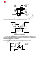
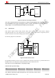
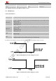
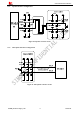
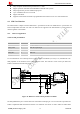
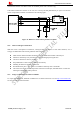
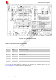
Table Of Contents
- Version History
- 1. Introduction
- 2. SIM800 Overview
- 3. Package Information
- 4. Application Interface
- 4.1. Power Supply
- 4.2. Power on/down SIM800
- 4.3. Power Saving Mode
- 4.4. RTC Backup
- 4.5. Serial Port and USB Interface
- 4.6. RI Behaviors
- 4.7. Audio Interfaces
- 4.8. Bluetooth
- 4.9. SIM Card Interface
- 4.10. PCM Interface
- 4.11. Keypad Interface
- 4.12. I2C BUS
- 4.13. General Purpose Input/Output (GPIO)
- 4.14. ADC
- 4.15. PWM
- 4.16. Network Status Indication
- 4.17. Operating Status Indication
- 4.18. KPLED
- 4.19. RF Synchronization Signal
- 4.20. Antenna Interface
- 5. PCB Layout
- 6. Electrical, Reliability and Radio Characteristics
- 6.1 Absolute Maximum Ratings
- 6.2 Recommended Operating Conditions
- 6.3 Digital Interface Characteristics
- 6.4 SIM Card Interface Characteristics
- 6.5 SIM_VDD Characteristics
- 6.6 VDD_EXT Characteristics
- 6.7 VRTC Characteristics
- 6.8 Current Consumption (VBAT=4V)
- 6.9 Electro-Static Discharge
- 6.10 Radio Characteristics
- 6.11 Module RF Receive Sensitivity
- 6.12 Module Operating Frequencies
- 7. Manufacturing
- 8. Appendix

Smart Machine Smart Decision
VDD_EXT
4.7K
47K
RXD
4.7K
MCUTXD
Module
Customer
VDD_EXT
MCUVDD
Figure 23: RX level converting by transistor
Note: The recommend Transistors’ part numbers are 2SC4617TLR and PBHV8115Z. when update firmware
via the TXD/RXD circuit as figure 22 and figure 23 shows, customer should make sure the VDD_EXT has
voltage output, or a external LDO should be added to power VDD_EXT.
4.5.3 USB Interface
USB interface supports software debug function. When power on the module, connect VBUS, USB_DP,
USB_DM and GND to PC, then install the driver successfully, a UART port could be recognized by the PC,
customer could achieve the software Debug purpose with this UART port.
The following diagram is recommended:
Figure 24: USB reference circuit
The maximum allowable cap load of TVS on USB data line should be less than 5pF (e.g. ESD9L5.0ST5G and
ESD9M5.0ST5G). The USB_DP and USB_DM should be routed in differential traces.
Note: please reserve the USB interface or test point for debug.
Table 10: VBUS operation voltage
Pin Min Typ Max Unit
VBUS 4.3 5 7 V
Note: VBUS is only used for USB inserting detection, can not be used as a power source.
SIM800_Hardware Design_V1.05 32 2014-03-25