
Sim800 hardware design v1.05
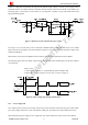
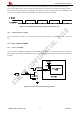
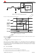
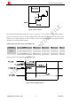
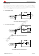
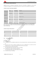
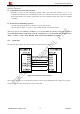
Table Of Contents
- Version History
- 1. Introduction
- 2. SIM800 Overview
- 3. Package Information
- 4. Application Interface
- 4.1. Power Supply
- 4.2. Power on/down SIM800
- 4.3. Power Saving Mode
- 4.4. RTC Backup
- 4.5. Serial Port and USB Interface
- 4.6. RI Behaviors
- 4.7. Audio Interfaces
- 4.8. Bluetooth
- 4.9. SIM Card Interface
- 4.10. PCM Interface
- 4.11. Keypad Interface
- 4.12. I2C BUS
- 4.13. General Purpose Input/Output (GPIO)
- 4.14. ADC
- 4.15. PWM
- 4.16. Network Status Indication
- 4.17. Operating Status Indication
- 4.18. KPLED
- 4.19. RF Synchronization Signal
- 4.20. Antenna Interface
- 5. PCB Layout
- 6. Electrical, Reliability and Radio Characteristics
- 6.1 Absolute Maximum Ratings
- 6.2 Recommended Operating Conditions
- 6.3 Digital Interface Characteristics
- 6.4 SIM Card Interface Characteristics
- 6.5 SIM_VDD Characteristics
- 6.6 VDD_EXT Characteristics
- 6.7 VRTC Characteristics
- 6.8 Current Consumption (VBAT=4V)
- 6.9 Electro-Static Discharge
- 6.10 Radio Characteristics
- 6.11 Module RF Receive Sensitivity
- 6.12 Module Operating Frequencies
- 7. Manufacturing
- 8. Appendix

Smart Machine Smart Decision
4.5. Serial Port and USB Interface
SIM800 provides one unbalanced asynchronous serial port. The module is designed as a DCE (Data
Communication Equipment). The following figure shows the connection between module and client (DTE).
Table 8: Serial port and USB pin definition
Name Pin number Function
UART_DTR 3 Data terminal ready
UART_RI 4 Ring indicator
UART_DCD 5 Data carrier detect
CTS 7 Clear to send
RTS 8 Request to send
TXD 9 Transmit data
Serial port
RXD 10 Receive data
VBUS 24 USB power supply
USB_DP 27 USB data line positive
USB
interface
USB_DM 28 USB data line minus
Note: Hardware flow control is disabled by default. The AT command “AT+IFC=2,2” can enable hardware
flow control .The AT command “AT+IFC=0,0”can disable hardware flow control. For more details, please
refer to document [1].
Table 9: Serial port characteristics
Symbol Min Max Unit
V
IL
0 0.3 V
V
IH
2.5 2.8 V
V
OL
0 0.1 V
V
OH
2.7 2.8 V
4.5.1 Function of Serial Port
Serial port:
z Full modem device.
z Contains data lines TXD and RXD, hardware flow control lines RTS and CTS, status lines DTR, DCD and
RI.
z Serial port can be used for CSD FAX, GPRS service and AT communication. It can also be used for
multiplex function. For details about multiplex function, please refer to table 11.
z Serial port supports the following baud rates:
1200, 2400, 4800, 9600, 19200, 38400, 57600 and 115200bps
z Autobauding only supports the following baud rates:
1200, 2400, 4800, 9600, 19200, 38400, 57600 and 115200bps
z The default setting is autobauding.
SIM800_Hardware Design_V1.05 29 2014-03-25