
Sim800 hardware design v1.05
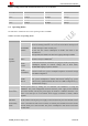
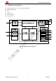
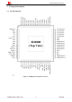
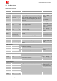
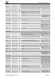
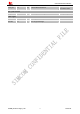
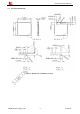
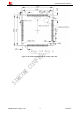
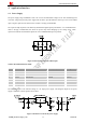
Table Of Contents
- Version History
- 1. Introduction
- 2. SIM800 Overview
- 3. Package Information
- 4. Application Interface
- 4.1. Power Supply
- 4.2. Power on/down SIM800
- 4.3. Power Saving Mode
- 4.4. RTC Backup
- 4.5. Serial Port and USB Interface
- 4.6. RI Behaviors
- 4.7. Audio Interfaces
- 4.8. Bluetooth
- 4.9. SIM Card Interface
- 4.10. PCM Interface
- 4.11. Keypad Interface
- 4.12. I2C BUS
- 4.13. General Purpose Input/Output (GPIO)
- 4.14. ADC
- 4.15. PWM
- 4.16. Network Status Indication
- 4.17. Operating Status Indication
- 4.18. KPLED
- 4.19. RF Synchronization Signal
- 4.20. Antenna Interface
- 5. PCB Layout
- 6. Electrical, Reliability and Radio Characteristics
- 6.1 Absolute Maximum Ratings
- 6.2 Recommended Operating Conditions
- 6.3 Digital Interface Characteristics
- 6.4 SIM Card Interface Characteristics
- 6.5 SIM_VDD Characteristics
- 6.6 VDD_EXT Characteristics
- 6.7 VRTC Characteristics
- 6.8 Current Consumption (VBAT=4V)
- 6.9 Electro-Static Discharge
- 6.10 Radio Characteristics
- 6.11 Module RF Receive Sensitivity
- 6.12 Module Operating Frequencies
- 7. Manufacturing
- 8. Appendix

Smart Machine Smart Decision
4. Application Interface
4.1. Power Supply
The power supply range of SIM800 is from 3.4V to 4.4V. Recommended voltage is 4.0V. The transmitting burst
will cause voltage drop and the power supply must be able to provide sufficient current up to 2A. For the VBAT
input, a bypass capacitor (low ESR) such as a 100µF is strongly recommended.
The 33pF and 10pF capacitors can effectively eliminate the high frequency interference. A 5.1V/500mW Zener
diode is strongly recommended, the diode can prevent chip from damaging by the voltage surge. These
capacitors and Zener diode should be placed as close to SIM800 VBAT pins as possible.
Figure 5: Reference circuit of the VBAT input
Table 5: Recommended Zener diode
Vendor Part number Power (watts) Package
1 On semi MMSZ5231BT1G 500mW SOD123
2 cj-elec MMSZ5231B 500mW SOD123
3 Prisemi PZ3D4V2H 500mW SOD323
4 Prisemi PZ5D4V2H 500mW SOD523
5 Vishay MMSZ4689-V 500mW SOD123
6 Crownpo CDZ55C5V1SM 500mW 0805
The following figure is the reference design of +5V input power supply. The designed output for the power
supply is 4.1V, thus a linear regulator can be used.
Figure 6: Reference circuit of the power supply
SIM800_Hardware Design_V1.05 20 2014-03-25