
Sim800 hardware design v1.05
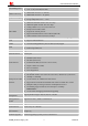
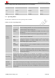
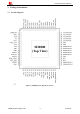
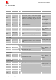
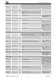
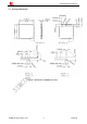
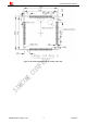
Table Of Contents
- Version History
- 1. Introduction
- 2. SIM800 Overview
- 3. Package Information
- 4. Application Interface
- 4.1. Power Supply
- 4.2. Power on/down SIM800
- 4.3. Power Saving Mode
- 4.4. RTC Backup
- 4.5. Serial Port and USB Interface
- 4.6. RI Behaviors
- 4.7. Audio Interfaces
- 4.8. Bluetooth
- 4.9. SIM Card Interface
- 4.10. PCM Interface
- 4.11. Keypad Interface
- 4.12. I2C BUS
- 4.13. General Purpose Input/Output (GPIO)
- 4.14. ADC
- 4.15. PWM
- 4.16. Network Status Indication
- 4.17. Operating Status Indication
- 4.18. KPLED
- 4.19. RF Synchronization Signal
- 4.20. Antenna Interface
- 5. PCB Layout
- 6. Electrical, Reliability and Radio Characteristics
- 6.1 Absolute Maximum Ratings
- 6.2 Recommended Operating Conditions
- 6.3 Digital Interface Characteristics
- 6.4 SIM Card Interface Characteristics
- 6.5 SIM_VDD Characteristics
- 6.6 VDD_EXT Characteristics
- 6.7 VRTC Characteristics
- 6.8 Current Consumption (VBAT=4V)
- 6.9 Electro-Static Discharge
- 6.10 Radio Characteristics
- 6.11 Module RF Receive Sensitivity
- 6.12 Module Operating Frequencies
- 7. Manufacturing
- 8. Appendix

Smart Machine Smart Decision
SIM800_Hardware Design_V1.05 16 2014-03-25
ROW2 42 O
ROW1 43 O
ROW0 44 O
GPIO
GPIO17 11 I/O
GPIO19 13 I/O
Programmable general purpose input and
output.
NETLIGHT 52 O Network status
STATUS 66 O Power on status
Can not multiplex with
GPIO function.
Serial port
UART_DTR 3 I Data terminal ready
UART_RI 4 O Ring indicator
UART_DCD 5 O Data carrier detect
CTS 7 O Clear to send
RTS 8 I Request to send
TXD 9 O Transmit data
RXD 10 I Receive data
Keep floating if
unused.
USB interface
VBUS 24 I
USB_DP 27 I/O
USB_DM 28 I/O
Debug and firmware upgrading
Keep floating if
unused.
ADC
ADC 25 I 10 bit general analog to digital converter
Keep floating if
unused.
PWM
PWM1/GPI
O22
35 O
Pulse-width modulation, multiplex with
GPIO22.
PWM2/GPI
O23
36 O
Pulse-width modulation, multiplex with
GPIO23.
Keep floating if
unused.
I2C
SDA 37 I/O I2C serial bus data
SCL 38 O I2C serial bus clock
Internal pulled up to
2.8V via 4.7K
SIM interface
SIM_VDD 30 O
Voltage supply for SIM card. Support 1.8V or
3V for SIM card
SIM_DATA 31 I/O SIM data input/output
SIM_CLK 32 O SIM clock
SIM_RST 33 O SIM reset
SIM_PRESE
NCE
34 I SIM card detection
All signals of SIM
interface should be
protected against ESD
with a TVS diode
array.
Antenna
RF_ANT 60 I/O Connect GSM antenna
Impendence must be
controlled to 50.