
Sim800 hardware design v1.05
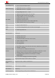
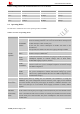
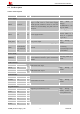
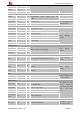
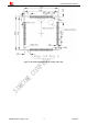
Table Of Contents
- Version History
- 1. Introduction
- 2. SIM800 Overview
- 3. Package Information
- 4. Application Interface
- 4.1. Power Supply
- 4.2. Power on/down SIM800
- 4.3. Power Saving Mode
- 4.4. RTC Backup
- 4.5. Serial Port and USB Interface
- 4.6. RI Behaviors
- 4.7. Audio Interfaces
- 4.8. Bluetooth
- 4.9. SIM Card Interface
- 4.10. PCM Interface
- 4.11. Keypad Interface
- 4.12. I2C BUS
- 4.13. General Purpose Input/Output (GPIO)
- 4.14. ADC
- 4.15. PWM
- 4.16. Network Status Indication
- 4.17. Operating Status Indication
- 4.18. KPLED
- 4.19. RF Synchronization Signal
- 4.20. Antenna Interface
- 5. PCB Layout
- 6. Electrical, Reliability and Radio Characteristics
- 6.1 Absolute Maximum Ratings
- 6.2 Recommended Operating Conditions
- 6.3 Digital Interface Characteristics
- 6.4 SIM Card Interface Characteristics
- 6.5 SIM_VDD Characteristics
- 6.6 VDD_EXT Characteristics
- 6.7 VRTC Characteristics
- 6.8 Current Consumption (VBAT=4V)
- 6.9 Electro-Static Discharge
- 6.10 Radio Characteristics
- 6.11 Module RF Receive Sensitivity
- 6.12 Module Operating Frequencies
- 7. Manufacturing
- 8. Appendix

Smart Machine Smart Decision
SIM800_Hardware Design_V1.05 15 2014-03-25
3.2. Pin Description
Table 4: Pin description
Pin name Pin number I/O Description Comment
Power supply
VBAT 55,56,57 I
SIM800 supplies 3 VBAT pins, and the power
range is from 3.4V to 4.4V. Power supply
should provide sufficient current so that the
module can work normally; the peak current is
nearly 2A.
Zener diode is
Strongly
recommended to anti
surge on VBAT.
VRTC 26 I/O Power supply for RTC
It is recommended to
connect VRTC to a
battery or a capacitor
(e.g. 4.7uF).
VDD_EXT 15 O 2.8V power output
Keep floating if
unused.
GND
2,17,18,29,39,
45,46,54,58,5
9,61,62,63,64,
65
Ground
Recommend
connecting
62,63,64,65pin to the
power GND.
Power on/off
PWRKEY 1 I
PWRKEY should be pulled low at least 1
second and then released to power on/down the
module.
Internally pulled up to
VBAT.
Audio interface
MICP 19
MICN 20
I Differential audio input
SPKP 21
SPKN 22
O Differential audio output
Keep floating if
unused.
PCM interface
PCMOUT 6 O
PCMIN 12 I
PCMSYNC 14 O
PCMCLK 68 I
PCM interface for audio
Keep floating if
unused.
Keypad interface
COL4 47 I
COL3 48 I
COL2 49 I
COL1 50 I
COL0 51 I
ROW4 40 O
ROW3 41 O
Support up to 50 buttons (5*5*2) Keep floating if
unused. (COL0 can
not be pulled down).