
Hardware Design V1.00
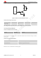
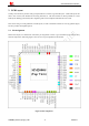
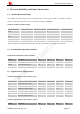
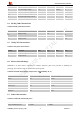
Table Of Contents
- Version History
- 1. Introduction
- 2. SIM2000S Overview
- 3. Package Information
- 4. Application Interface
- 4.1. Power Supply
- 4.2. Power on/down Scenarios
- 4.3. Power Saving Mode
- 4.4. Serial Port and Debug Interface
- 4.5. RI behaviors
- 4.6. Audio Interfaces
- 4.7. RUIM Card Interface
- 4.8. PCM Interface
- 4.9. Keypad Interface
- 4.10. I2C Bus
- 4.11. General Purpose Input/Output (GPIO)
- 4.12. ADC
- 4.13. PWM
- 4.14. Network Status Indication
- 4.15. NETLIGHT Multiplexing Function
- 4.16. Operating Status Indication
- 4.17. Antenna Interface
- 5. PCB Layout
- 6. Electrical, Reliability and Radio Characteristics
- 7. Manufacturing
- 8. Appendix

Smart Machine Smart Decision
SIM2000S_Hardware_Design_V1.00 46 2014-02-27
6. Electrical, Reliability and Radio Characteristics
6.1 Absolute Maximum Ratings
The absolute maximum ratings stated in following table are stress ratings under non-operating conditions.
Stresses beyond any of these limits will cause permanent damage to SIM2000S.
Table 38: Absolute maximum ratings
Symbol Min Typ Max Unit
VBAT 6 V
Current 0 - 1 A
VBUS 7 V
II* 8 mA
IO* 8 mA
*
These parameters are for digital interface pins, such as keypad, GPIO, I2C, UART, LCD and PCM.
6.2 Recommended Operating Conditions
Table 39: Recommended operating conditions
Symbol Parameter Min Typ Max Unit
VBAT Power supply voltage 3.4 3.8 4.4 V
TOPER Operating temperature -40 +25 +85 ℃
TSTG Storage temperature -45 +90 ℃
6.3 Digital Interface Characteristics
Table 40: Digital interface characteristics (1.8V)
Symbol Parameter Min Typ Max Unit
V
IH
High-level input voltage 1.17 1.83 V
V
IL
Low-level input voltage -0.3 0.63 V
V
OH
High-level output voltage 1.35 1.8 V
V
OL
Low-level output voltage 0 0.45 V
I
IH
IIH Input high leakage current 1 uA
I
IL
Input low leakage current -1 uA
Table 41: Digital interface characteristics (2.85V)
Symbol Parameter Min Typ Max Unit