
Hardware Design V1.00
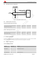
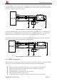
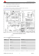
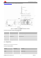
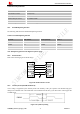
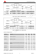
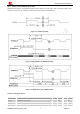
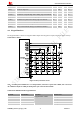
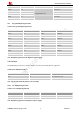
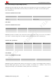
Table Of Contents
- Version History
- 1. Introduction
- 2. SIM2000S Overview
- 3. Package Information
- 4. Application Interface
- 4.1. Power Supply
- 4.2. Power on/down Scenarios
- 4.3. Power Saving Mode
- 4.4. Serial Port and Debug Interface
- 4.5. RI behaviors
- 4.6. Audio Interfaces
- 4.7. RUIM Card Interface
- 4.8. PCM Interface
- 4.9. Keypad Interface
- 4.10. I2C Bus
- 4.11. General Purpose Input/Output (GPIO)
- 4.12. ADC
- 4.13. PWM
- 4.14. Network Status Indication
- 4.15. NETLIGHT Multiplexing Function
- 4.16. Operating Status Indication
- 4.17. Antenna Interface
- 5. PCB Layout
- 6. Electrical, Reliability and Radio Characteristics
- 7. Manufacturing
- 8. Appendix

Smart Machine Smart Decision
T(clk) PCMCLK cycle time 488 ns
T(clkh) PCMCLK high time 244 ns
T(clkl) PCMCLK low time 244 ns
T(susync) PCMSYNC setup time high before falling edge of PCMCLK 60 ns
T(hsync) PCMSYNC hold time after falling edge of PCMCLK 60 ns
T(sudin) PCMDIN setup time before falling edge of PCMCLK 50 ns
T(hdin) PCMDIN hold time after falling edge of PCMCLK 10 ns
T(pdout) Delay from PCMCLK rising to PCMDOUT valid 350 ns
T(zdout) Delay from PCMCLK falling to PCMDOUT HIGH-Z 160 ns
4.9. Keypad Interface
The keypad interface consists of 5 keypad column outputs and 5 keypad row inputs, which can support 25 keys.
Connections as below:
Figure 35: Keys reference circuit
Note
:
According to the traditional 5 * 5 to design buttons, when there is spare COL or ROW, user can execute
AT command to define as GPIO for details please refer to the relevant manuals.
Table 24: Pin definition of the keypad interface
Pin name Pin number Function Default state
KBC0 51 Pull up
KBC1 50 Pull up
KBC2 49 Pull up
KBC3 48
Keypad matrix column
Pull up
SIM2000S_Hardware_Design_V1.00 38 2014-02-27