
Hardware Design V1.00
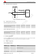
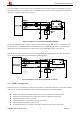
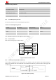
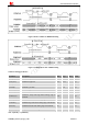
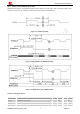
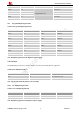
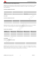
Table Of Contents
- Version History
- 1. Introduction
- 2. SIM2000S Overview
- 3. Package Information
- 4. Application Interface
- 4.1. Power Supply
- 4.2. Power on/down Scenarios
- 4.3. Power Saving Mode
- 4.4. Serial Port and Debug Interface
- 4.5. RI behaviors
- 4.6. Audio Interfaces
- 4.7. RUIM Card Interface
- 4.8. PCM Interface
- 4.9. Keypad Interface
- 4.10. I2C Bus
- 4.11. General Purpose Input/Output (GPIO)
- 4.12. ADC
- 4.13. PWM
- 4.14. Network Status Indication
- 4.15. NETLIGHT Multiplexing Function
- 4.16. Operating Status Indication
- 4.17. Antenna Interface
- 5. PCB Layout
- 6. Electrical, Reliability and Radio Characteristics
- 7. Manufacturing
- 8. Appendix

Smart Machine Smart Decision
Table 20: PCM specification
Parameter Specification
Line Interface Format Linear(Fixed)
Data length 8/16bits
PCM Clock/Sync Source Slave/Master Mode
PCM Clock Rate 256Khz、2.048Mhz
Data Ordering MSB/LSB both support
4.8.1. PCM Multiplexing Function
The following table shows the detailed multiplexing function.
Table 21: PCM multiplexing function
Pin name Pin number Mode 0(default) Mode 1
PCMCLK 11 PCMCLK GPIO8
PCMIN 12 PCMIN GPIO9
PCMOUT 13 PCMOUT GPIO10
PCMSYNC 14 PCMSYNC GPIO11
Note: Multiplexing function needs different software supply.
4.8.2. PCM Interface
Refer to the following figure for PCM design:
Figure 28: PCM reference circuit
4.8.3. Auxiliary PCM (128 KHz PCM clock)
u-law coding is supported by the auxiliary PCM. The auxiliary codec port operates with standard long-sync
timing and a 128 KHz clock. The PCMSYNC runs at 8 KHz with 50% duty cycle. Most u-law codec support the
128 KHz clock.
Figure 29: Synchrony timing
SIM2000S_Hardware_Design_V1.00 35 2014-02-27