
Hardware Design V1.00
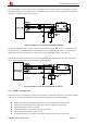
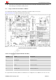
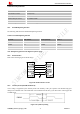
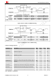
Table Of Contents
- Version History
- 1. Introduction
- 2. SIM2000S Overview
- 3. Package Information
- 4. Application Interface
- 4.1. Power Supply
- 4.2. Power on/down Scenarios
- 4.3. Power Saving Mode
- 4.4. Serial Port and Debug Interface
- 4.5. RI behaviors
- 4.6. Audio Interfaces
- 4.7. RUIM Card Interface
- 4.8. PCM Interface
- 4.9. Keypad Interface
- 4.10. I2C Bus
- 4.11. General Purpose Input/Output (GPIO)
- 4.12. ADC
- 4.13. PWM
- 4.14. Network Status Indication
- 4.15. NETLIGHT Multiplexing Function
- 4.16. Operating Status Indication
- 4.17. Antenna Interface
- 5. PCB Layout
- 6. Electrical, Reliability and Radio Characteristics
- 7. Manufacturing
- 8. Appendix

Smart Machine Smart Decision
z Add some TVS and the parasitic capacitance should not exceed 50pF, and 22Ohm resistor in serials,
the RUIM signal could enhance ESD protection.
4.7.3. Design Considerations for RUIM Card Holder
For 8 pins RUIM card holder, SIMCom recommends to use Molex 91228. User can visit
http://www.molex.com
for more information about the holder.
Figure 26: Molex 91228 RUIM card holder
Table 17: Pin description (Amphenol RUIM card holder)
Pin name Signal Description
C1 RUIM_VDD RUIM card power supply
C2 RUIM_RST RUIM card reset
C3 RUIM_CLK RUIM card clock
C4 GND Connect to GND
C5 GND Connect to GND
C6 VPP Not connect
C7 RUIM_DATA RUIM card data I/O
C8 RUIM_PRESENCE Detect RUIM card presence
For 6-pin RUIM card holder, SIMCom recommends to use Amphenol C707 10M006 5122. User can visit
SIM2000S_Hardware_Design_V1.00 33 2014-02-27