
Hardware Design V1.00
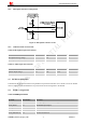
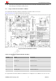
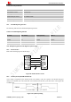
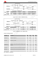
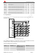
Table Of Contents
- Version History
- 1. Introduction
- 2. SIM2000S Overview
- 3. Package Information
- 4. Application Interface
- 4.1. Power Supply
- 4.2. Power on/down Scenarios
- 4.3. Power Saving Mode
- 4.4. Serial Port and Debug Interface
- 4.5. RI behaviors
- 4.6. Audio Interfaces
- 4.7. RUIM Card Interface
- 4.8. PCM Interface
- 4.9. Keypad Interface
- 4.10. I2C Bus
- 4.11. General Purpose Input/Output (GPIO)
- 4.12. ADC
- 4.13. PWM
- 4.14. Network Status Indication
- 4.15. NETLIGHT Multiplexing Function
- 4.16. Operating Status Indication
- 4.17. Antenna Interface
- 5. PCB Layout
- 6. Electrical, Reliability and Radio Characteristics
- 7. Manufacturing
- 8. Appendix

Smart Machine Smart Decision
4.6.2. Microphone Interfaces Configuration
Figure 23: Microphone reference circuit
4.6.3. Audio Electronic Characteristic
Table 14: Microphone input characteristics
Parameter Min Typ Max Unit
Microphone biasing voltage 1.8 V
Input impedance(differential) 16 20 24 K
Table 15: Audio output characteristics
Parameter Min Typ Max Unit
Speaker output voltage 1.11 1.25 1.40 V
RL=32, THD=4% 38.5 48.8 61.3 mW
4.7. RUIM Card Interface
It should meet the protocol and electrical requirements as specified in ISO/IEC 7816-3. Both 1.8V and 3V RUIM
cards are supported. The RUIM interface is powered from an internal regulator in the module.
4.7.1. RUIM Card Application
Table 16: RUIM pin definition
Pin name Pin number Function
RUIM_VDD 30 Voltage supply for RUIM card. Support 1.8V or 3V RUIM card
RUIM_DATA 31 RUIM data input/output
RUIM_CLK 32 RUIM clock
RUIM_RST 33 RUIM reset
RUIM_PRESENCE 34 RUIM card detection
SIM2000S_Hardware_Design_V1.00 31 2014-02-27