SIM2000S_Hardware_Design_V1.
Smart Machine Smart Decision Document Title SIM2000S Hardware Design Version 1.00 Date 2014-02-27 Status Release Document Control ID SIM2000S_Hardware_Design_V1.00 General Notes SIMCom offers this information as a service to its customers, to support application and engineering efforts that use the products designed by SIMCom. The information provided is based upon requirements specifically provided to SIMCom by the customers.
Smart Machine Smart Decision Contents Version History............................................................................................................ 8 1. Introduction.......................................................................................................... 9 2. SIM2000S Overview ............................................................................................ 9 2.1. 2.2. 2.3. 3. Package Information ...............................................................
Smart Machine Smart Decision 4.8.1. 4.8.2. 4.8.3. 4.8.4. 4.9. 4.9.1 PCM Multiplexing Function ............................................................................................................... 35 PCM Interface ..................................................................................................................................... 35 Auxiliary PCM (128 KHz PCM clock)...............................................................................................
Smart Machine Smart Decision Table Index TABLE 1: SIM2000S KEY FEATURES............................................................................................................................ 9 TABLE 2: OVERVIEW OF OPERATING MODES........................................................................................................ 11 TABLE 3: PIN DESCRIPTION .......................................................................................................................................
Smart Machine Smart Decision TABLE 46: OPERATING FREQUENCIES..................................................................................................................... 48 TABLE 47: CONDUCTED RECEIVE SENSITIVITY ................................................................................................... 48 TABLE 48: MOISTURE SENSITIVITY LEVEL AND FLOOR LIFE ........................................................................... 50 TABLE 49: BAKING REQUIREMENTS ..........................
Smart Machine Smart Decision Figure Index FIGURE 1: SIM2000S FUNCTIONAL DIAGRAM ....................................................................................................... 12 FIGURE 2: SIM2000S PIN OUT DIAGRAM (TOP VIEW)........................................................................................... 13 FIGURE 3: DIMENSIONS OF SIM2000S (UNIT: MM)................................................................................................
Smart Machine Smart Decision Version History Date Version Description of change Author 2014-02-27 1.00 draft Yanwu.Wang; Haibing.Ye SIM2000S_Hardware_Design_V1.
Smart Machine Smart Decision 1. Introduction This document describes SIM2000S hardware interface in great detail. This document can help user to quickly understand SIM2000S interface specifications, electrical and mechanical details. With the help of this document and other SIM2000S application notes, user guide, users can use SIM2000S to design various applications quickly. 2. SIM2000S Overview SIM2000S is a single CDMA module, which works on frequency 450MHz (BC5).
Smart Machine Smart Decision z z z z z z z z z z z Serial port and debug port z z z EVRC-B(or 4GV) Microphone: 8kHz sampling rate,16bit Audio AGC PCM post processing Echo Cancellation 8,16 or 32kHz Tx path sampling rate Serial port: Full modem interface with status and control lines, unbalanced, asynchronous 115200bps Can be used for AT commands or data stream Support RTS/CTS hardware handshake and software ON/OFF flow control Programmable parameters 1. Data size 2. Stop bits 3. Parity 4. Bit rate 5.
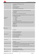
Smart Machine Smart Decision Physical characteristics Size: 24*24*3mm Weight: 3.4g Firmware upgrade USB port 2.2. Operating Mode The table below summarizes the various operating modes of SIM2000S. Table 2: Overview of operating modes Mode Normal operation Function CDMA SLEEP Module will automatically go into sleep mode if the conditions of sleep mode are enabling and there is no on air and no hardware interrupt (such as GPIO interrupt or data on serial port).
Smart Machine Smart Decision Figure 1: SIM2000S functional diagram SIM2000S_Hardware_Design_V1.
Smart Machine Smart Decision 3. Package Information 3.1. Pin out Diagram Figure 2: SIM2000S pin out diagram (Top view) 3.2. Pin Description Table 3: Pin description Pin name Pin number SIM2000S_Hardware_Design_V1.
Smart Machine Smart Decision Power supply VBAT 55,56,57 I 3.4~4.4 Power supply VDD_EXT 15 O 2.85 2.85V output power supply GND 2,17,18,29,39, 45,46,53,54, 58,59,61,62, 63,64,65 Ground 1 PWRKEY should be pulled low at least 1 second and then released to power on/down the module. If it is unused, keep open. Power on/down PWRKEY I 1.8 Pulled up internally.
Smart Machine Smart Decision KBC0 51 keypad column 1 KBC1 50 keypad column 1 KBC2 49 keypad column 2 KBC3 48 keypad column 3 KBC4 47 keypad column 4 GPIO33 67 GPIO34 68 I/O GPIO33 1.8 GPIO34 Serial port RXD 10 I Receive data TXD 9 O Transmit data RTS 8 I Request to send CTS 7 O DCD 5 O Data carrier detect RI 4 O Ring indicator DTR 3 I Data terminal ready Voltage supply for RUIM card. Support 1.8V or 3V RUIM card 2.
Smart Machine Smart Decision 3.3. Package Dimensions Figure 3: Dimensions of SIM2000S (Unit: mm) SIM2000S_Hardware_Design_V1.
Smart Machine Smart Decision Figure 4: Recommended PCB footprint outline (Unit: mm) SIM2000S_Hardware_Design_V1.
Smart Machine Smart Decision 4. Application Interface 4.1. Power Supply The power supply range of SIM2000S is from 3.4V to 4.4V. Recommended voltage is 3.8V. The power supply must be able to provide sufficient current up to 600mA. For the VBAT input, a bypass capacitor (low ESR) such as a 100 µF is strongly recommended. A 5.1V/500mW Zener diode is strongly recommended, the diode can prevent chip from damaging by the voltage surge.
Smart Machine Smart Decision If there is a high drop-out between the input and the desired output (VBAT), a DC-DC power supply will be preferable because of its better efficiency especially with the 600mA current of the module. The following figure is the reference circuit. Figure 7: Reference circuit of the DC-DC power supply The single 3.7V Li-ion cell battery can be connected to SIM2000S VBAT pins directly.
Smart Machine Smart Decision Figure 8: Powered on/down module using transistor 1.8V 200K PWRKEY Power on/down logic MODULE Figure 9: Powered on/down module using button The power on timing is illustrated as in the following figure. Figure 10: Timing of power on module When power on procedure is completed, SIM2000S will send following URC to indicate that the module is ready to operate at fixed baud rate. RDY SIM2000S_Hardware_Design_V1.
Smart Machine Smart Decision 4.2.2. Power down SIM2000S SIM2000S will be powered down in the following situations: z Normal power down procedure: power down SIM2000S by the PWRKEY pin. z Normal power down procedure: power down SIM2000S by AT command “AT+CPOWD=1”. z Abnormal power down: over-voltage or under-voltage automatic power down. z Abnormal power down: over-temperature or under-temperature automatic power down. 4.2.2.1.
Smart Machine Smart Decision If the voltage ≥ 4.3V, the following URC will be reported: OVER-VOLTAGE WARNNING If the voltage < 3.4V, the following URC will be reported, and the module will be automatically powered down. UNDER-VOLTAGE POWER DOWN If the voltage > 4.4V, the following URC will be reported, and the module will be automatically powered down. OVER-VOLTAGE POWER DOWN At this moment, AT commands can not be executed any more. The status light will be powered off at this time. 4.2.2.4.
Smart Machine Smart Decision The typical value of RESET pin at High level is 1.8V, so for the 1.8V, customer could use MCU’s GPIO to drive this pin directly, cascading some resistors could enhance the ESD performance but the value should not be too big; otherwise the level of RESET could be lower than the threshold value; for RESET hardware parameters user can refer to the table below: Table 5: Electronic characteristic of the RESET pin Pin name RESET Symbol Min VIH 1.5 Typ Unit V VIL TVL Max 0.
Smart Machine Smart Decision Symbol Parameter Conditions Value Unit Power down mode 12 uA Sleep mode (CMU2000) 2 mA Cellular 450M Cellular 450M MAX POWER IVBAT VBAT current Voice call (CMU2000) Cellular 450M CDMA POWER-60dBm Cellular 450M MIN POWER Idle CH=1 461.35 CH=100 512.13 CH=193 506.79 CH=1 93.86 CH=100 96.35 CH=193 94.28 CH=1 87.68 CH=100 89.38 CH=193 88.29 CMU2000 (without USB) mA mA mA 13.
Smart Machine Smart Decision Table 7: Serial port and Debug pin definition Serial port Debug port USB port Pin name Pin number Function DTR 3 Data terminal ready RI 4 Ring indicator DCD 5 Data carrier detect CTS 7 Request to send RTS 8 Clear to send TXD 9 Transmit data RXD 10 Receive data DBG_TXD 27 DBG_RXD 28 VBUS 6 USB power supply USB_DP 23 USB differential data, (+) side USB_DM 24 USB differential data, (-) side Used for debug Note: Hardware flow control is dis
Smart Machine Smart Decision Figure 14: Connection of the serial interfaces The following figure shows the connection of the inner module. Figure 15: Connection of the inner module If the voltage of UART is 3.3V, the following reference circuits are recommended. SIM2000S_Hardware_Design_V1.
Smart Machine Smart Decision Figure 16: Level matching circuit 4.4.3 USB Interface SIM2000S could achieve software debug function through USB interface. When powering on the module, connecting VBUS, USB_DP, USB_DM, and GND to PC, then installing the driver following the prompts, a USB port could be recognized by PC, customer could achieve the software Debug with USB port.
Smart Machine Smart Decision Table 9: VBUS operation voltage Pin Min Typ Max Unit VBUS 4.4 5 5.5 V 4.4.4 Software Upgrade and Debug Customer could upgrade module’s firmware through USB. If upgrading through USB port, it is necessary to power on SIM2000S first, and then connect VBUS, USB_DP, USB_DM, and GND to PC.
Smart Machine Smart Decision State RI response Standby High Voice call The pin is changed to low. When any of the following events occurs, the pin will be changed to high: (1)Establish the call (2)Hang up the call Data call The pin is changed to low. When any of the following events occurs, the pin will be changed to high: (1)Establish the call (2)Hang up the call SMS The pin is changed to low, and kept low for 120ms when a SMS is received. Then it is changed to high.
Smart Machine Smart Decision However, if the module is used as caller, the RI will remain high. Please refer to the following figure. Figure 21: RI behaviour as a caller 4.6. Audio Interfaces SIM2000S provides an analog inputs (MICP; MICN), which could be used for electret microphone. The module also provides an analog output (SPKP; SPKN).
Smart Machine Smart Decision 4.6.2. Microphone Interfaces Configuration Figure 23: Microphone reference circuit 4.6.3. Audio Electronic Characteristic Table 14: Microphone input characteristics Parameter Min Typ Microphone biasing voltage Input impedance(differential) Max 1.8 Unit V 16 20 24 KΩ Parameter Min Typ Max Unit Speaker output voltage 1.11 1.25 1.40 V RL=32Ω, THD=4% 38.5 48.8 61.3 mW Table 15: Audio output characteristics 4.7.
Smart Machine Smart Decision It is recommended to use an ESD protection component such as ON (http://onsemi.com) SMF12CT1G. That the RUIM peripheral circuit should be close to the RUIM card socket. The reference circuit of the 8-pin RUIM card holder is illustrated in the following figure. Figure 24: Reference circuit of the 8-pin RUIM card holder The RUIM_PRESENCE pin is used for detection of the RUIM card hot plug in. User can select the 8-pin RUIM card holder to implement RUIM card detection function.
Smart Machine Smart Decision z 4.7.3. Add some TVS and the parasitic capacitance should not exceed 50pF, and 22Ohm resistor in serials, the RUIM signal could enhance ESD protection. Design Considerations for RUIM Card Holder For 8 pins RUIM card holder, SIMCom recommends to use Molex 91228. User can visit http://www.molex.com for more information about the holder.
Smart Machine Smart Decision http://www.amphenol.com for more information about the holder. Figure 27: Amphenol C707 10M006 5122 RUIM card holder Table 18: Pin description (Amphenol RUIM card holder) Pin name Signal Description C1 RUIM_VDD RUIM card power supply C2 RUIM_RST RUIM card reset C3 RUIM_CLK RUIM card clock C5 GND Connect to GND C6 VPP Not connect C7 RUIM_DATA RUIM card data I/O 4.8.
Smart Machine Smart Decision Table 20: PCM specification Parameter Specification Line Interface Format Linear(Fixed) Data length 8/16bits PCM Clock/Sync Source Slave/Master Mode PCM Clock Rate 256Khz、2.048Mhz Data Ordering MSB/LSB both support 4.8.1. PCM Multiplexing Function The following table shows the detailed multiplexing function.
Smart Machine Smart Decision Figure 30: EXT CODEC to MODULE timing Figure 31: MODULE to EXT CODEC timing Table 22: Timing parameters Parameter Description T(auxsync) PCMSYNC cycle time T(auxsynch) PCMSYNC high time T(auxsyncl) PCMSYNC low time T(auxclk)* PCMCLK cycle time T(auxclkh) PCMCLK high time T(auxclkl) Min Typ Max Unit 125 μs 62.4 62.5 μs 62.4 62.5 μs 7.8 μs 3.8 3.9 μs PCMCLK low time 3.8 3.
Smart Machine Smart Decision 4.8.4. Primary PCM (2048KHz PCM clock) SIM2000S also supports 2.048 MHz PCM data and sync timing for υ-law codec. This is called the primary PCM interface. User can use AT command to take the mode you want as discussed above.
Smart Machine Smart Decision T(clk) PCMCLK cycle time 488 ns T(clkh) PCMCLK high time 244 ns T(clkl) PCMCLK low time 244 ns T(susync) PCMSYNC setup time high before falling edge of PCMCLK 60 ns T(hsync) PCMSYNC hold time after falling edge of PCMCLK 60 ns T(sudin) PCMDIN setup time before falling edge of PCMCLK 50 ns T(hdin) PCMDIN hold time after falling edge of PCMCLK 10 ns T(pdout) Delay from PCMCLK rising to PCMDOUT valid T(zdout) Delay from PCMCLK falling to PCMDOUT HIGH
Smart Machine Smart Decision KBC4 47 Pull up KBR0 44 Pull down KBR1 43 Pull down KBR2 42 KBR3 41 Pull down KBR4 40 Pull down 4.9.
Smart Machine Smart Decision 4.11. General Purpose Input/Output (GPIO) SIM2000S provides 2 GPIO pins. The output voltage level of the GPIO can be set by AT command “AT+ SGPIO”. The input voltage level of the GPIO can also be read by AT command “AT+ SGPIO”. For more details, please refer to document [1]. Table 28: Pin definition of the GPIO Pin name Pin number Reset state GPIO33 67 Output, pull down GPIO34 68 Output, pull up 4.12.
Smart Machine Smart Decision A typical recommended circuit of the PWM driver buzzer is shown in the following figure. VBA T MODULE 4.7K PWM 47K Figure 36: Reference circuit of PWM driver buzzer Table 32: Buzzer output characteristics Parameter Min Typ Max Unit Output voltage 2.85 V Output current 6 mA Note: PWM pin must be kept at low power level when module is in the power on procedure. 4.14.
Smart Machine Smart Decision Figure 37: Reference circuit of NETLIGHT 4.15. NETLIGHT Multiplexing Function Table 35: NETLIGHT multiplexing function Pin name Pin number Mode 0(default) Mode 1 NETLIGHT 52 NETLIGHT GPIO31 Note: Multiplexing function need different software supply. 4.16. Operating Status Indication The pin66 is for operating status indication of the module. The pin output is high when module is powered on, and output is low when module is powered off.
Smart Machine Smart Decision connected to module’s antenna pad through micro-strip line or other type of RF trace and the trace impedance must be controlled in 50Ω. SIMCom recommends that the total insertion loss between the antenna pad and antenna should meet the following requirements: ● CDMA 450MHZ<0.5dB To facilitate the antenna tuning and certification test, a RF connector and an antenna matching circuit should be added. The following figure is the recommended circuit.
Smart Machine Smart Decision 5. PCB Layout Usually, most electronic products with good performance are based on good PCB layout. A bad PCB layout will lead to lots of issues, like RUIM card not being detected, etc. The final solution for these problems is to redo PCB layout. Making good PCB layout at beginning will save development schedule and cost as well.
Smart Machine Smart Decision 5.2 Principle of PCB layout During layout, attention should be paid to the following interfaces, like Antenna, power supply, RUIM card interface, audio interface, and so on. 5.2.1 Antenna Interface The basis principle is that the length of trace between pin output and connector should be as short as possible in order to avoid coupling issue. Do not trace RF signal over across the board.
Smart Machine Smart Decision 6. Electrical, Reliability and Radio Characteristics 6.1 Absolute Maximum Ratings The absolute maximum ratings stated in following table are stress ratings under non-operating conditions. Stresses beyond any of these limits will cause permanent damage to SIM2000S.
Smart Machine Smart Decision VIH High-level input voltage 1.8525 - 2.88 V VIL Low-level input voltage -0.3 - 0.9975 V VOH High-level output voltage 2.4 - 2.85 V VOL Low-level output voltage 0 - 0.45 V IIH IIH Input high leakage current 1 uA IIL Input low leakage current 6.4 -1 uA RUIM_VDD Characteristics Table 42: RUIM_VDD characteristics Symbol Min Output voltage VO Typ Max 1.8 Unit V 3 Output current IO 6.
Smart Machine Smart Decision Table 46: Operating frequencies Frequency Receiving Transmission CDMA 450MHZ Block C 460~464.8MHz 450~454.8MHz Table 47: Conducted receive sensitivity Frequency Receive sensitivity(Typical) Receive sensitivity(Max) CDMA 450MHZ Block C -108dBm -106dBm SIM2000S_Hardware_Design_V1.
Smart Machine Smart Decision 7. Manufacturing 7.1. Top and Bottom View of SIM2000S Figure 40: Top and bottom view of SIM2000S 7.2. Typical Solder Reflow Profile Figure 41: Typical solder reflow profile SIM2000S_Hardware_Design_V1.
Smart Machine Smart Decision 7.3. The Moisture Sensitivity Level The moisture sensitivity level of SIM2000S module is 3. The modules should be mounted within 168 hours after unpacking in the environmental conditions of temperature <30℃ and relative humidity of <60% (RH).
Smart Machine Smart Decision 8. Appendix I. Related Documents Table 50: Related documents SN Document name [1] SIM2000S Series AT Command Manual [2] AN Serial Port SIM2000S_Hardware_Design_V1.
Smart Machine Smart Decision II.
Smart Machine Smart Decision NC Not connect III. Safety Caution Table 52: Safety caution Marks Requirements When in a hospital or other health care facility, observe the restrictions about the use of mobiles. Switch the cellular terminal or mobile off, medical equipment may be sensitive to not operate normally for RF energy interference. Switch off the cellular terminal or mobile before boarding an aircraft. Make sure it is switched off.
Smart Machine Smart Decision Contact us: Shanghai SIMCom Wireless Solutions Co.,Ltd. Address: Building A, SIM Technology Building, No. 633, Jinzhong Road, Shanghai, P. R. China 200335 Tel: +86 21 3252 3300 Fax: +86 21 3252 3020 URL: www.sim.com/wm SIM2000S_Hardware_Design_V1.