
Users Manual Part 2

SIM8260A_Hardware Design_V1.05
www.simcom.com 56 / 122
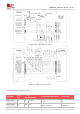
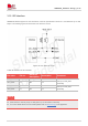
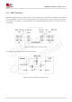
Figure 31: Audio codec reference circuit
The PCM interface is multiplexing with I2S interface. The default audio interface of the module is I2S.
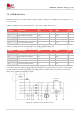
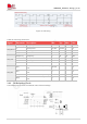
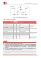
Table 36: The PCM interface is multiplexing with I2S interface
Pin name
Pin no.
Electrical
description
Description
Comment
I2S_DOUT/
PCM_DOUT
N1
DO
P3
I2S/PCM data output
Default is I2S
interface,
can be configured as
PCM interface by
software,
If unused, please
keep open
I2S_DIN/
PCM_DIN
R1
DI
P3
I2S/PCM data input
I2S_CLK/
PCM_CLK
P3
DO
P3
I2S/PCM clock output
I2S_WS/
PCM_SYNC
T3
DIO
P3
I2S word selection/
PCM synchronization signal
I2S_MCLK
L1
DO
P3
I2S master clock output
For more details about audio function, please refer to
Document [19]
in the appendix.
Codec ALC5616 supports 5-wire I2S by default. Software can configure the internal registers of
ACL5616 to configure 4-wire I2S (without I2S_MCLK signal) or 5-wire I2S (with I2S_MCLK signal)
interface.
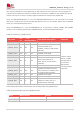
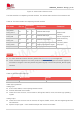
Table 37: Recommended audio list
Name
Manufacturer
Model
ALC5616
REALTEK
ALC5616-CGT
Audio layout guidelines:
Analog input
0.2mm trace widths; 0.2mm spacing between traces.
Pseudo differential route for MIC.
Isolate from noise sources, such as antenna, RF signals, SMPS, clocks, and other high speeding
signals.
Analog output
Isolate from noise sources such as antenna, RF signals, SMPS, clocks, and other digital signals with
fast transients.
Speaker output signal – route as differential pair with 0.5mm trace widths.
NOTE